 Products Home / Detectors / Amplified Detectors / Si Amplified Detectors / Si Fiber-Coupled Avalanche Photodetector
Si Fiber-Coupled Avalanche Photodetector
- Wavelength Range from 400 - 1100 nm
- Temperature Compensated and Variable Gain
- Integrated Flange Enables Direct Fiber Coupling Using Adapters
- FC/APC, FC/PC, LC/PC, and SC/PC Adapters Available
APDA2-A
FC/APC Fiber Connector Adapter, 350 - 700 nm
APDF2-B
FC/PC Fiber Connector Adapter, 600 - 1050 nm
APDL-A
LC/PC Fiber Connector Adapter, 350 - 700 nm
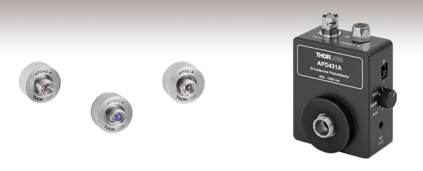
APD431A
Si Fiber-Coupled
Avalanche Photodetector


Please Wait
| Avalanche Photodiode Selection Guidea |
|---|
| Free-Space Si APDs |
| Fiber-Coupled Si APDs |
| Free-Space InGaAs APDs |
| Fiber-Coupled InGaAs APDs |
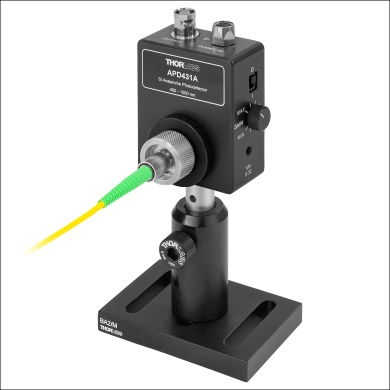 Click to Enlarge
The APD431A photodetector is connected to an optical fiber (sold separately) using the APDA2-A fiber connector adapter.
Features
- Wavelength Range from 400 to 1100 nm
- Temperature Compensated to Provide M Factor Stability of ≤±3% Over 18 to 28 °C
- Continuously Variable Gain with M Factor from 10 to 100
- Robust Fiber Coupling Using M12 x 0.5-Threaded Fiber Connector Adapters (Sold Below)
- Post Mountable in Three Orientations Using Universal 8-32 / M4 x 0.7 Taps
- LDS12B Power Supply Included
Thorlabs offers a Fiber-Coupled Silicon Avalanche Photodetector (APD) that is sensitive to light from 400 to 1100 nm. This temperature compensated photodetector features a variable gain and large usable bandwidth of DC to 400 MHz. It also features an externally M12 x 0.5-threaded flange for robust fiber coupling when used with our Fiber Connector Adapters sold below. With increased sensitivity and lower noise compared to standard PIN detectors, it is ideal for applications with low optical power levels.
In general, avalanche photodiodes use an internal gain mechanism to increase sensitivity. A high reverse bias voltage is applied to the diodes to create a strong electric field. When an incident photon generates an electron-hole pair, the electric field accelerates the electrons, leading to the production of secondary electrons by impact ionization. The resulting electron avalanche can produce a gain factor of several hundred times, described by a multiplication factor, M, that is a function of both the reverse bias voltage and temperature. In general, the M factor increases with lower temperatures and decreases with higher temperatures. Similarly, the M factor will increase when the reverse bias voltage is raised and decrease when the reverse bias voltage is lowered.
The APD431A photodetector offers a large usable bandwidth of DC to 400 MHz. It features an integrated thermistor that maintains an M factor stability of ±3% or better over 23 ± 5 °C by adjusting the bias voltage across the avalanche photodiode. It also features a variable gain that can be controlled by a knob on the right side of the housing, which varies the M factor from 10 to 100.
The orientation of the mechanical and electrical connections, combined with the compact design, ensures that the APD431A detector can fit into tight spaces. Three universal 8-32 / M4 x 0.7 mounting holes further ensure easy integration into complicated mechanical setups.
Fiber-Coupling and Mechanical Adapters
The APD431A photodetector is designed to offer robust fiber-coupling capabilities to our existing APD430A free-space avalanche photodetector. It features an externally M12 x 0.5-threaded flange that is compatible with our M12 x 0.5-threaded fiber connector adapters (sold below), allowing for quick fiber coupling with high reproducbility. The adapters are optimized for single mode fibers, and for multimode fibers with a 200 μm core and NA = 0.22; however, they can be used with all optical fibers with some loss of coupling efficiency. Options are available for FC/APC, FC/PC, LC/PC, or SC/PC fiber connections, and with coatings for 350 - 700 nm or 600 - 1050 nm.
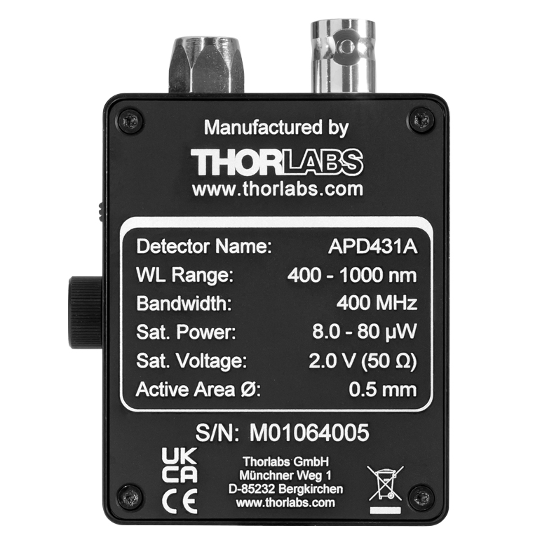 Click to Enlarge
The back plate of the APD431A photodetector is engraved with the detector's specifications.
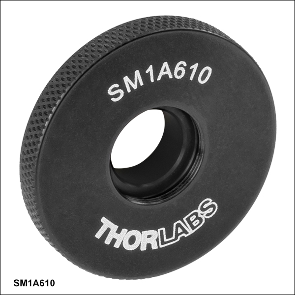
Additionally, Thorlabs offers the SM1A610 mechanical adapter (sold below), which features internal M12 x 0.5 threads to connect directly to the APD431A photodetector, and external SM1 threads for compatibility with SM1-threaded components. This adapter allows the APD431A photodetector to be used as a free-space detector with standard optomechanical components; however, if space is a concern, the APD430A photodetector provides a more compact design as a free-space Si APD.
Please note that our free-space Si APDs can also support fiber coupling through the use of a fiber collimation package, focusing lens, and X-Y translator (please see the Fiber Coupling tab here for more information). However, the externally M12 x 0.5-threaded flange featured on the APD431A photodetector provides a more stable and compact means for fiber coupling. This M12 x 0.5-threaded flange can be added to any of Thorlabs' Avalanche Photodetectors to provide robust fiber-coupling capabilities. Please contact Tech Support for more information
Power Supply
An LDS12B ±12 V linear power supply is included with the amplified photodetector; replacement power supplies are available below. The power supply features a three-way switch and can be plugged into any 50 to 60 Hz, 100 V / 120 V / 230 V power outlet. Before connecting the power supply to an outlet or to the detector, make sure that the power switches on both the power supply and the detector are in the off position. Hot-plugging is not recommended.
A complete list of all of our APDs can be found on the Selection Guide tab. Please note that our Single Photon Detectors are the only avalanche photodetectors suitable for single photon counting.
All technical data are valid at 23 ± 5 °C and 45% ± 15% relative humidity (non-condensing).
| Item # | APD431A |
|---|---|
| Detector Type | Silicon APD |
| Wavelength Range | 400 - 1000 nm |
| Output Bandwidth (3 dB)a | DC - 400 MHz |
| Threading | External M12 x 0.5 |
| Active Area Diameter | 0.5 mm |
| Max Responsivity | 53 A/W @ 800 nm (M = 100) |
| M Factor | 10 - 100 (Continuous) |
| M Factor Temperature Stability | ±2% (Typical); ±3% (Max) |
| Transimpedance Gainb | 5 kV/A (50 Ω Termination) 10 kV/A (High-Z Termination) |
| Max Conversion Gainc | 5.3 × 10⁵ V/W |
| CW Saturation Powerd | 8.0 µW @ 800 nm, M = 100 80 µW @ 800 nm, M = 10 |
| Max Input Powere | 1 mW |
| Minimum NEPf | 0.14 pW/√Hz (DC - 100 MHz) |
| Integrated Noise | 5.5 nW (RMS, DC - 400 MHz) |
| Electrical Output, Impedance | BNC, 50 Ω |
| Max Output Voltage Swingb | 2.0 V (50 Ω Termination) 4.1 V (High-Z Termination) |
| DC Offset Electrical Output | <±3 mV |
| Included Power Supplyg | LDS12B, ±12 V @ 250 mA (100/120/230 VAC, 50 - 60 Hz, Switchable) |
| General | |
| Operating Temperature Range | 0 to 40 °C (Non-Condensing) |
| Storage Temperature Range | -40 to 70 °C |
| Dimensions (H x W x D) | 2.93" x 2.20" x 1.33" (74.5 mm x 55.8 mm x 33.7 mm) |
| Weight | 0.122 kg |
 Click to Enlarge
 Click to Enlarge
Click Here for Raw Data
Typical output frequency response curve for the APD431A photodetector.
 Click to Enlarge
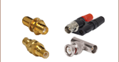
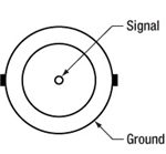
BNC Female Output (Photodetector)
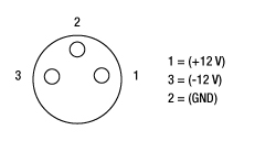
APD Male (Power Cables)

APD Female (Photodetector)
Pulsed Laser Emission: Power and Energy Calculations

Determining whether emission from a pulsed laser is compatible with a device or application can require referencing parameters that are not supplied by the laser's manufacturer. When this is the case, the necessary parameters can typically be calculated from the available information. Calculating peak pulse power, average power, pulse energy, and related parameters can be necessary to achieve desired outcomes including:
- Protecting biological samples from harm.
- Measuring the pulsed laser emission without damaging photodetectors and other sensors.
- Exciting fluorescence and non-linear effects in materials.
Pulsed laser radiation parameters are illustrated in Figure 1 and described in the table. For quick reference, a list of equations are provided below. The document available for download provides this information, as well as an introduction to pulsed laser emission, an overview of relationships among the different parameters, and guidance for applying the calculations.
|
Equations: |
||||
 |
and |  |
||
 |
||||
 |
||||
 |
||||
Peak power and average power calculated from each other: |
||||
 |
and |  |
||
| Peak power calculated from average power and duty cycle*: | ||||
 |
*Duty cycle ( ) is the fraction of time during which there is laser pulse emission. ) is the fraction of time during which there is laser pulse emission. |
|||

Click to Enlarge
Figure 1: Parameters used to describe pulsed laser emission are indicated in the plot (above) and described in the table (below). Pulse energy (E) is the shaded area under the pulse curve. Pulse energy is, equivalently, the area of the diagonally hashed region.
| Parameter | Symbol | Units | Description | ||
|---|---|---|---|---|---|
| Pulse Energy | E | Joules [J] | A measure of one pulse's total emission, which is the only light emitted by the laser over the entire period. The pulse energy equals the shaded area, which is equivalent to the area covered by diagonal hash marks. | ||
| Period | Δt | Seconds [s] | The amount of time between the start of one pulse and the start of the next. | ||
| Average Power | Pavg | Watts [W] | The height on the optical power axis, if the energy emitted by the pulse were uniformly spread over the entire period. | ||
| Instantaneous Power | P | Watts [W] | The optical power at a single, specific point in time. | ||
| Peak Power | Ppeak | Watts [W] | The maximum instantaneous optical power output by the laser. | ||
| Pulse Width |  |
Seconds [s] | A measure of the time between the beginning and end of the pulse, typically based on the full width half maximum (FWHM) of the pulse shape. Also called pulse duration. | ||
| Repetition Rate | frep | Hertz [Hz] | The frequency with which pulses are emitted. Equal to the reciprocal of the period. | ||
Example Calculation:
Is it safe to use a detector with a specified maximum peak optical input power of 75 mW to measure the following pulsed laser emission?
- Average Power: 1 mW
- Repetition Rate: 85 MHz
- Pulse Width: 10 fs
The energy per pulse:

seems low, but the peak pulse power is:

It is not safe to use the detector to measure this pulsed laser emission, since the peak power of the pulses is >5 orders of magnitude higher than the detector's maximum peak optical input power.
Avalanche Photodetector Selection Guide
| Item # | Detector Type |
Wavelength Range |
3 dB Bandwidth | Active Area Diameter |
M Factor | Typical Max Responsivity |
Max Conversion Gaina |
Variable Gain |
Temperature Compensated |
Fiber-Coupledb |
|---|---|---|---|---|---|---|---|---|---|---|
| APD440A2 | UV Enhanced Silicon APD |
200 - 1000 nm | DC - 0.1 MHz | 1 mm | 5 - 50 | 25 A/W @ 600 nm (M = 50) | 1.25 x 10⁹ V/W | - | ||
| APD410A2 | DC - 10 MHz | 0.5 mm | 5 - 50 | 25 A/W @ 600 nm (M = 50) | 12.5 x 10⁶ V/W | - | ||||
| APD130A2 | DC - 50 MHz | 1 mm | 50 | 25 A/W @ 600 nm (M = 50) | 2.5 x 10⁶ V/W | - | - | |||
| APD430A2 | DC - 400 MHz | 0.2 mm | 10 - 100 | 50 A/W @ 600 nm (M = 100) | 5.0 x 10⁵ V/W | - | ||||
| APD410 | 5 - 900 MHzc | 0.2 mm | 50 | 22 A/W @ 650 nm (M = 50) | 4.5 x 10⁴ V/Wd | - | ||||
| APD440A | Silicon APD | 400 - 1000 nm | DC - 0.1 MHz | 1 mm | 10 - 100 | 53 A/W @ 800 nm (M = 100) | 2.65 x 10⁹ V/W | - | ||
| APD410A | DC - 10 MHz | 1.0 mm | 10 - 100 | 53 A/W @ 800 nm (M=100) | 26.5 x 10⁶ V/W | - | ||||
| APD130A | DC - 50 MHz | 1 mm | 50 | 25 A/W @ 800 nm (M = 50) | 2.5 x 10⁶ V/W | - | - | |||
| APD430A | DC - 400 MHz | 0.5 mm | 10 - 100 | 53 A/W @ 800 nm (M = 100) | 5.3 x 10⁵ V/W | - | ||||
| APD431A | DC - 400 MHze | 0.5 mm | 10 - 100 | 53 A/W @ 800 nm (M = 100) | 5.3 x 10⁵ V/W | |||||
| APD210 | 5 - 1000 MHzc | 0.5 mm | 100 | 50 A/W @ 800 nm (M = 100) | 2.5 x 10⁵ V/Wf | - | ||||
| APD130C | InGaAs APD | 900 - 1700 nm | DC - 50 MHz | 0.2 mm | 10 | 9 A/W @ 1500 nm (M = 10) | 0.9 x 10⁶ V/W | - | - | |
| APD410C | DC - 10 MHz | 0.2 mm | 4 - 20 | 18 A/W @ 1550 nm (M = 20) | 9.0 x 10⁶ V/W | - | ||||
| APD430C | DC - 400 MHz | 0.2 mm | 4 - 20 | 18 A/W @ 1550 nm (M = 20) | 1.8 x 10⁵ V/W | - | ||||
| APD431C | DC - 400 MHze | 0.2 mm | 4 - 20 | 18 A/W @ 1550 nm (M = 20) | 1.8 x 10⁵ V/W | |||||
| APD450C | 1260 - 1620 nm | 0.3 - 1600 MHz | 1.5 mmg | 2 - 10 | 9 A/W @ 1550 nm (M = 10) | 45 × 103 V/W | - | |||
| APD310 | 850 - 1650 nm | 5 - 1000 MHzc | 0.04 mm | 30 | 0.9 A/W @ 1550 nm (M = 30) | 2.5 x 10⁴ V/Wh | - |
| Posted Comments: | |
| No Comments Posted |
| Item #a,b | Housing Featuresc |
Wavelength Range |
Output Bandwidth (3 dB)d | Threadinge | Active Area Diameter | Max Responsivity | Typical Performance Graph | Max Conversion Gainf | M Factor Adjustment Range | Minimum NEPg,h | Power Supply Included |
|---|---|---|---|---|---|---|---|---|---|---|---|
| APD431A |  |
DC - 400 MHz | External M12 x 0.5 |
0.5 mm | 53 A/W @ 800 nm (M = 100) |  Click Here for Raw Data |
5.3 × 10⁵ V/W | 10 - 100 (Continuous) | 0.14 pW/√Hz | Yesi |

 Zoom
Zoom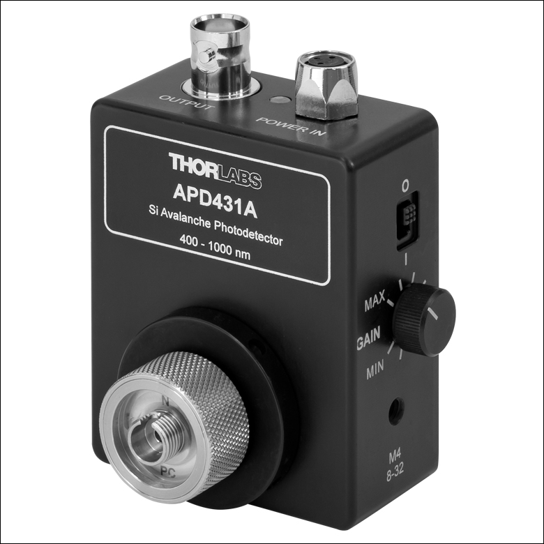 Click to Enlarge
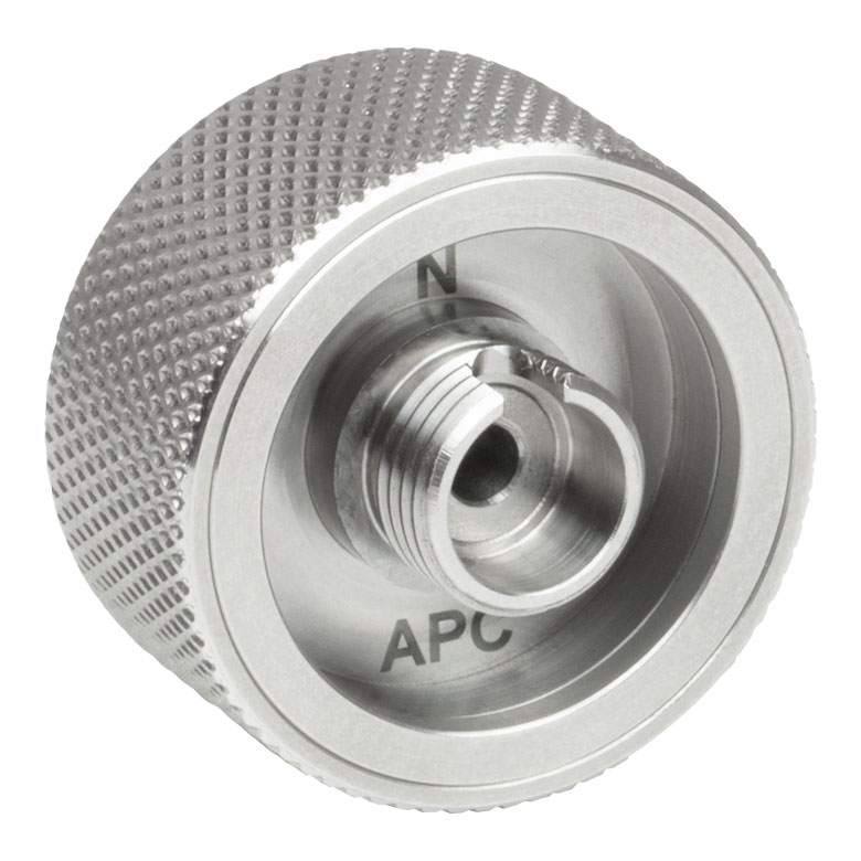
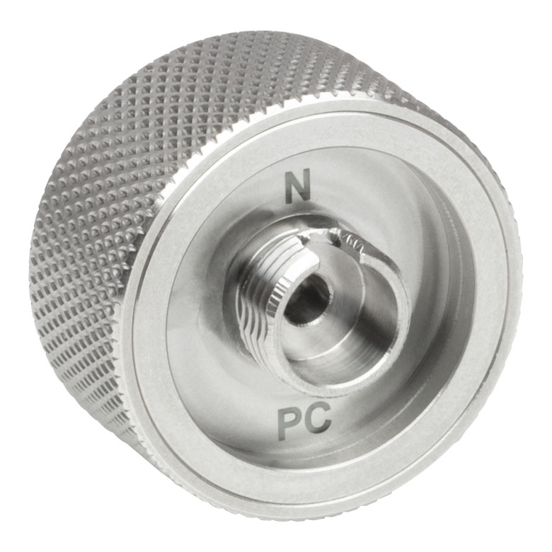
The APDF2-A Fiber Connector Adapter Mounted to the APD431A Photodetector
- Enable Fiber-Coupling to the APD431A Avalanche Photodetector (Sold Above)
- Compatible with Single Mode and Multimode Fibers
- Four Fiber Connection Options Available
- Two Coating Options Available for Visible Light Detection
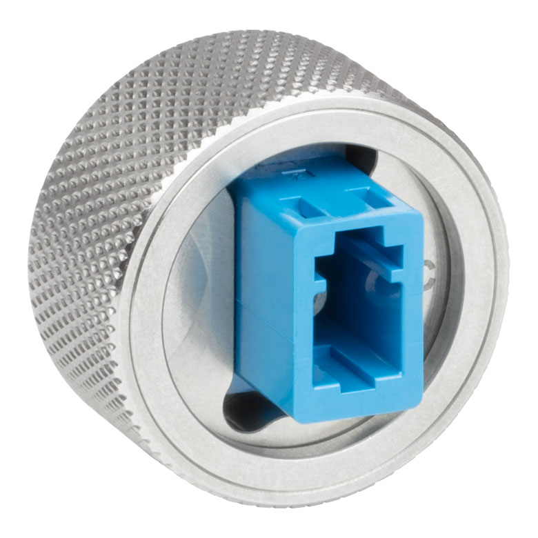
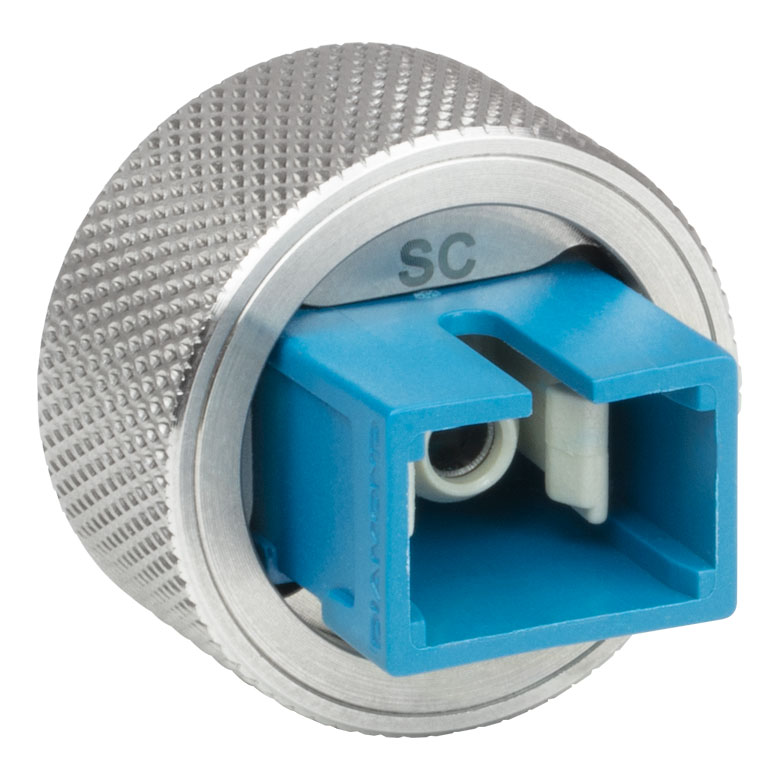
Thorlabs offers Fiber Connector Adapters that enable single-mode and multi-mode fibers to connect to our APD431A photodetector. These robust adapters allow for easy fiber coupling with high reproduciblity. Each adapter has a small footprint and can be directly mounted to the APD via M12 x 0.5 threading. They feature a built-in Molded Glass Aspheric Lens and are optimized for single mode fibers, and for multimode fibers with a 200 μm core and NA = 0.22; however, they can be used with all optical fibers with some loss of coupling efficiency. Options are available for FC/APC, FC/PC, LC/PC, and SC/PC fiber connections, and with coatings for 350 - 700 nm and 600 - 1050 nm. For adapters with coatings for infrared light detection, please see our InGaAs APD fiber connector adapters.
| Item # | APDA2-A | APDA2-B | APDF2-A | APDF2-B | APDL-A | APDL-B | APDS-A | APDS-B |
|---|---|---|---|---|---|---|---|---|
| Fiber Connector Typea | FC/APC Narrow-Key (2.0 mm) |
FC/PC Narrow-Key (2.0 mm) |
LC/PC | SC/PC | ||||
| Built-In Lens | 355440-A | 355440-B | 355440-A | 355440-B | 355440-A | 355440-B | 355440-A | 355440-B |
| AR Coating Rangeb | 350 - 700 nm (-A Coating)c |
600 - 1050 nm (-B Coating)d |
350 - 700 nm (-A Coating)c |
600 - 1050 nm (-B Coating)d |
350 - 700 nm (-A Coating)c |
600 - 1050 nm (-B Coating)d |
350 - 700 nm (-A Coating)c |
600 - 1050 nm (-B Coating)d |
 Threads and Internal M12 x 0.5 Threads")
 Zoom
Zoom Click to Enlarge
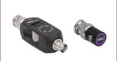
An SM1M10 lens tube is connected to the APD431A photodetector using the SM1A610 adapter.
- Compatible with the APD431A Avalanche Photodetector (Sold Above) and Other Externally M12 x 0.5-Threaded Components
- Compatible with SM1-Threaded Components
The SM1A610 adapter allows the APD431A photodetector to be used as a free-space detector with standard optomechanics. This robust adapter connects directly to the APD431A photodetector via internal M12 x 0.5 threading and features external SM1 (1.035"-40) threads for use with standard SM1-threaded components.

 Zoom
Zoom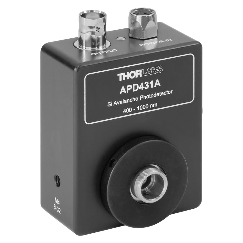
LDS12B Male Power Cable
- Replacement Power Supply for APD431A Avalanche Photodetector (Sold Above)
- ±12 VDC Power Output
- Current Limit Enabling Short Circuit and Overload Protection
- On/Off Switch with LED Indicator
- Switchable AC Input Voltage (100, 120, or 230 VAC)
- 2 m (6.6 ft) Cable with LUMBERG RSMV3 Male Connector
- UL and CE Compliant
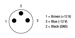
The LDS12B ±12 VDC Regulated Linear Power Supply is intended as a replacement for the supply included with our APD431A avalanche photodetector sold above. The cord has three pins: one for ground, one for +12 V, and one for -12 V (see diagram above). This power supply ships with a location-specific power cord. This power supply can also be used with the PDA series of amplified photodetectors, PDB series of balanced photodetectors, PMM series of photomultiplier modules, and the FSAC autocorrelator for femtosecond lasers.