30 mm Cage Cubes for Fluorescence Filter Sets
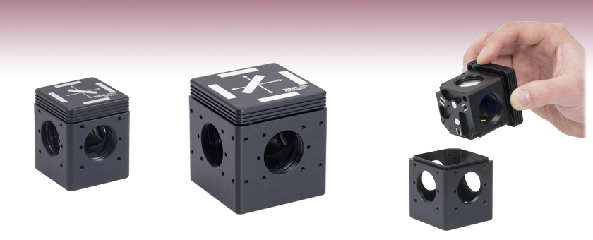
- Quickly Interchange Filter Sets with Repeatable Alignment
- Mount Emission and Excitation Filters, and a Rectangular Dichroic Mirror
- 30 mm Cage System Compatible Cubes for Ø25 mm or Ø32 mm Filters
DFM1L
30 mm Cage Cube for
Ø25 mm Fluorescence Filters,
SM1-Threaded Ports
Cube Inserts and Base Also Available Separately
Magnetic Coupling Offers Repeatable Alignment of a Fluorescence Filter Set within a Cage System
DFM32R1
30 mm Cage Cube for
Ø32 mm Fluorescence Filters,
SM30-Threaded Ports

Please Wait
Click to Enlarge
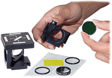
The DFM1 filter cube shown here can hold a fluorescence filter set: one dichroic mirror, one excitation filter, and one emission filter.
Click to Enlarge
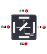
The filter cubes have two excitation (EX) and two emission (EM) filter ports. Ports labeled with the same number should be used together.
Features
- Kinematic 30 mm Cage Cubes for Holding Fluorescence Filter Set (Sold Separately)
- Two Cube Sizes Available for Mounting:
- Ø25 mm Round and 25 mm x 36 mm Rectangular Optics
- Ø32 mm Round and 32 mm x 44 mm Rectangular Optics
- 30 mm Cage System Compatible
- At Least One Emission Port with 3° Tilt to Reduce Undesired Reflections
- Individual Cube Inserts, Base, and Cover Plate Also Available
- Easily Swap Inserts in Cage Aligned Cubes
- 30 mm Cage Cube Connectors for Connecting Two Cubes Side by Side (Sold Separately Below)
Thorlabs' Fluorescence Filter Cubes are designed to hold a dichroic mirror, excitation filter, and emission filter in a cube that is 30 mm cage-system-compatible for home-built microscopy setups. Each filter cube consists of a base and removable insert that accepts fluorescence filter set components or other optics. Additional inserts are available to easily exchange alternate sets of optics within an aligned setup (see photo on the bottom right). This enables switching between fluorescence imaging of different wavelengths or changing the direction of the reflected light.
In addition, the cube inserts have four ports for Ø25 mm filters (DFM1 Series) or Ø32 mm filters (DFM32 Series); the excitation and emission filters can be mounted in two possible configurations (see the diagram to the right). At least one of the ports is oriented at a 3° angle with respect to the face in order to reduce undesired reflections. The DFM1T1 insert, for instance, features one angled port (labeled EM2 in the diagram to the upper right). Further information on the number of angled ports for each insert can be found in the table and subgroups below.
To help keep track of your filter sets, spaces are provided on the top to write labels for the mounted filters and mirrors. The cube insert is designed to be inserted in a single orientation with respect to the cube base, so it is important to orient the full cube assembly in the proper direction. The DFM1 cage cubes and cage cube inserts on this page are available with either a left- or right-turning orientation, while the DFM32 cubes and insert are only available with a right-turning orientation.
The cube bases are equipped with three bottom-located 1/4"-20 (M6) tapped holes, which provide direct compatibility with our Ø1" posts or Ø1.5" posts. Alternately, an AE8E25E (AE4M6M) thread adapter (sold separately) can be used for compatibility with our Ø1/2" posts.
Click to Enlarge
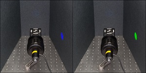
A DFM1T1 insert with an MDF-GFP filter set (left) or an MDF-TRITC filter set (right) can be swapped to change between imaging different fluorescent samples.
| Item # | DFM1(/M) | DFM1L(/M) | DFM32R1(/M) |
|---|---|---|---|
| Included Insert Item # | DFM1T1 | DFM1T3 | DFM32T1 |
| Emission and Excitation Filter Diameter | Ø25 mma | Ø25 mma | Ø32 mm |
| Dichroic Size | 25 mm x 36 mm | 25 mm x 36 mm | 32 mm x 44 mm |
| Emission Port Clear Aperture | Ø20.0 mm | Ø20.0 mm | Ø30.0 mm |
| Excitation Port Clear Aperture | Ø22.9 mm | Ø22.9 mm | Ø30.0 mm |
| # of Angled Emission Ports | 1 | 2 | 2 |
| Right or Left - Turning | Right | Left | Right |
| Cube Connector | C4W-CC | C4W-CC | DFM32-CC |
| # | Product Description | Qty. | Photo (Click to Enlarge) |
|---|---|---|---|
| 1 | DFM1 - Kinematic Fluorescence Filter Cube |
1 |  |
| 2 | Microscopy Filters | 1 Set |  |
| 3 | SM1B3 - Lens Tube Bellows | 1 |  |
| 4 | SM1ZM - Non-Rotating SM1 Zoom Housing |
1 |  |
| 5 | Focusing Lens Inside Zoom Housing |
1 |  |
| 6 | ST1XY-D - XY Translator with Differential Drives |
1 |  |
| 7 | Precision Pinhole Between XY Translator and Photodetector |
1 |  |
| 8 | Photodetector SM1-Compatible Photodetector |
1 |  |
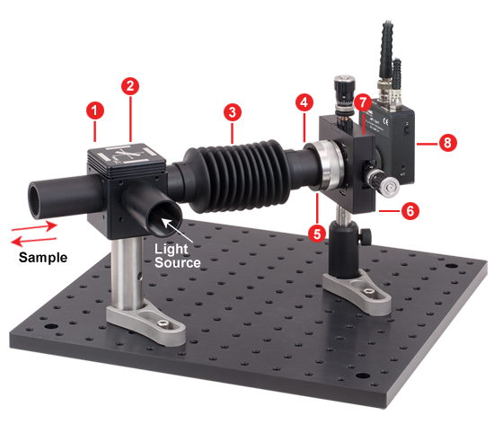
DFM1 Filter Cubes - Optic Alignment in a Confocal Microscope Detection Module
The DFM1 is ideal for integrating filter sets into a custom microscopy setup. The following example of a partial confocal microscope uses a DFM1 Fluorescence Filter Cube (denoted by 1 in the image below) containing a Microscopy Filter Set (2) and an APD130A(/M) Photodetector (8). A lens (5) located inside the SM1ZM High-Precision Zoom Housing (4) focuses the beam onto a precision pinhole (7) located just before the avalanche photodetector's detector element. The SM1ZM zoom housing is mounted directly onto the ST1XY-D XY Translation Mount with Differential Adjusters (6), creating a compact XYZ mount. SM1 Lens Tubes and the SM1B3 Lens Tube Bellows (3) allow for a light-tight connection without inhibiting the free movement of the XYZ mount.
Components used in the configuration pictured below are listed in the table to the right. These parts, along with SM1 Lens Tubes and 1" Post Assemblies, are sold separately.
| Posted Comments: | |
Thomas Dzelzainis
(posted 2024-02-29 18:50:36.24) Hi,
I have a question about the Fluorescence filter cube inserts. For the right turning insert, DFM1T1, the technical drawing says that only one port in transmission is angularly off-set, while the other three are at normal incidence, but for the left turning insert, DFM1T3, the technical drawing indicates that both the ports for the transmitted paths are angularly offset (there are two arrows, although the wording is still singular). I would have assumed that both are identical and would have both transmission ports angularly offset. Can you clarify the situation?
Many thanks,
Thomas cdolbashian
(posted 2024-03-11 03:39:34.0) Thank you for reaching out to us with this inquiry Thomas. The drawings do seem a bit confusing as they seem to be nominally the same part with different turning directions. As you mention the wording in the drawing is still singular, when referring to this angle, despite 2 indications. The left hand turning insert does indeed have 2 angled ports, while the right turning has only 1. I have contacted you directly to address any remaining concerns. Felix Lauhoff
(posted 2023-03-08 09:49:36.753) Hello ThorLabs-Team,
Do you can explain me why the emmissionport of the Filtercube is aligned 3° off-axis?
My guess is that light reflection into the objective prevented.
Thank you for your help. jdelia
(posted 2023-03-09 04:12:23.0) Thank you for contacting Thorlabs. There is a 3 degree tilt to the emission port to reduce unwanted reflections in the end user's setup as you suggested. Basilio Javier Garcia
(posted 2020-09-18 19:17:18.05) DFM1 filter cube application note seems to have a erratum.
It is probably a DFM1L cube instead a DFM1 one llamb
(posted 2020-09-29 10:20:06.0) Thank you for your feedback. The "Applications" tab image and parts list does use the DFM1 cube. Its initial mounting happens to be used in a more "left-turning" orientation because of the location of the light source. I have reached out to you directly to discuss this further as well. Ben Garber
(posted 2020-06-26 12:53:35.537) This mount is listed as kinematic but I don't see where the adjusters are to change the angle of the optic. Is it actually a kinematic mount, or do you just mean that the optic mount can be replaced? YLohia
(posted 2020-07-09 09:40:54.0) Hello, thank you for your feedback. While the mirror mounts are removable, these cube mounts do not have tip-tilt ability. We will make this more clear in our documentation. |
| Kinematic Cage Cubes Selection Guide (Click Image to Enlarge) | |||||
|---|---|---|---|---|---|
| Type | Empty Cubes for Fluorescence Filters |
Empty Cubes for Beamsplitters |
Empty Cubes for Right-Angle Optics |
Beam-Turning Cubes with Pre-Mounted Prism Mirrors | Multimode Fiber Optic Filter Cube |
| 16 mm Cage Cubes |  Full Web Presentation |
- | - | - | - |
| 30 mm Cage Cubes |  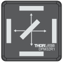 Full Web Presentation |
 Full Web Presentation |
 Full Web Presentation |
 Full Web Presentation |
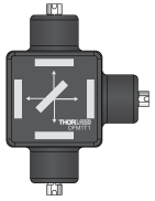 Full Web Presentation |
| 60 mm Cage Cubes | 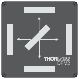 Full Web Presentation |
- |  Full Web Presentation |
- | - |

Click to Enlarge
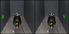
The DFM1L Cube (Left Panel) and DFM1 Cube (Right Panel) used to direct a filtered beam to the left and right, respectively. Light from an MCWHL7 LED was directed via the MDF-TRITC Filter Set installed in each cube.
| DFM1(/M) & DFM1L(/M) Compatible Filters | ||
|---|---|---|
| Type | Dimensions | Thickness |
| Excitation | Ø25 mm | 5.0 mm |
| Emission | Ø25 mm | 3.5 mm |
| Dichroic | Min: 25.0 mm x 35.6 mm Max: 25.2 mm x 36.0 mm |
Min: 1.0 mm Max: 2.0 mma |
- Cubes for Mounting Ø25 mm Round Optics and 25 mm x 36 mm Rectangular Optic Fluorescence Filter Sets
- DFM1(/M): Right-Turning Orientation
- DFM1L(/M): Left-Turning Orientation
- Four 4-40 Tapped Holes Around Each SM1-Threaded (1.035"-40) Port Enable 30 mm Cage System Compatibility
- Three Bottom-Located 1/4"-20 (M6) Tapped Holes for Post Mounting
- Cube Accessories:
- Empty Kinematic Base
- Inserts for Exchanging User-Provided Filters or Mirror
- Cover Plate for Transmission without an Insert
Full Cubes
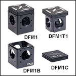
The DFM1(/M) and DFM1L(/M) Kinematic Fluorescence Filter Cubes each consist of a post-mountable cube base and a removable insert that mounts a fluorescence filter set (sold separately). The DFM1 holds a dichroic mirror in a right turning orientation, and the DFM1L in a left-turning orientation. Thus, using the DFM1 as opposed to the DFM1L results in a 180° difference in light output direction.
As shown in the animation to the upper right, the inserts are designed to hold a rectangular optic, such as a dichroic mirror, beamsplitter, or silver mirror. The DFM1 insert clamps the rectangular optic gently in place using a leaf spring that provides a uniform holding force to minimize stress. To mount the rectangular optic, remove the leaf spring using a Phillips #00 screwdriver and then insert the optic with the reflective coating face down. Only light force is needed to prevent the optic from moving; we recommend screwing in both screws most of the way before final tightening.
The DFM1 insert holds the round excitation and emission filters using the included SM1RR Retaining Rings, which can be tightened or loosened with our SPW606 or SPW602 Spanner Wrenches (sold separately). The insert is set within the SM1-Threaded base cube and has clear apertures of Ø22.9 mm and Ø20.0 mm for the excitation and emission ports, respectively.
Cube Base and Inserts
The DFM1T1 (included with the DFM1(/M) Cube) and DFM1T3 (included with the DFM1L(/M) Cube) Kinematic Fluorescence Filter Cube Inserts and DFM1B(/M) Base allow users to switch between different filter sets in an aligned experimental setup. The inserts hold the dichroic mirror in a right-turning (Item # DFM1T1) or left-turning (Item # DFM1T3) orientation (see image to the right showing the DFM1 cube and DFM1L cube). These items do not include fluorescence filters or a dichroic mirror.
For the DFM1T1 Cube Insert, one emission port is oriented at a 3° angle with respect to the face in order to reduce undesired reflections. For the DFM1T3 Cube Insert, both emission ports are oriented at 3° angles with respect to the face.
See the table to the right for acceptable optic sizes. Prior to mounting the rectangular dichroic mirror, please confirm that the optic is no greater than 2.0 mm thick. To mount dichroic mirrors thicker than 2.0 mm, we recommend using our Dichroic Cage Cube.
All four sides of the filter cube base have an SM1-threaded (1.035"-40) port for compatibility with our Ø1" lens tubes. The SM1 port is centered between four 4-40 tapped holes for compatibility with Ø6 mm cage rods in a 30 mm cage system, at an optical axis height of 1.25" or 30.0 mm from the bottom of the imperial or metric cube, respectively.
Cube Cover
For when a filter is not installed within the DFM1B(/M) cube base, we have the DFM1C Cage Cube Cover Plate to place on top. Additionally, we offer the SM1CP2 End Cap to minimize the amount of stray light entering through unused ports.

Click to Enlarge
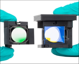
Opened DFM32T1 Filter Cube Insert showing spring plate (left) and filters.
- Cubes for Mounting Ø32 mm Round Optics and 32 mm x 44 mm Rectangular Optic
- DFM32R1(/M): Right-Turning Orientation
- Four 4-40 Tapped Holes Around Each SM30-Threaded (M30.5 x 0.5) Port Enable 30 mm Cage System Compatibility
- Three Bottom-Located 1/4"-20 (M6) Tapped Holes for Post Mounting
- Cube Accessories:
- Empty Kinematic Base
- Insert for Exchanging User-Provided Filters or Mirror
- Cover Plate for Shielding Stray Light
Full Cubes
The DFM32R1(/M) Kinematic Fluorescence Filter Cubes consist of a post-mountable cube base and a removable right-turning insert that mounts Ø32 mm round emission and excitation filters and 32 mm x 44 mm rectangular dichroics.
As shown in the animation to the right, the DFM32R1 insert uses a spring plate retention mechanism for holding the rectangular optic. To mount the optic, open the insert by unscrewing the two hex screws on the edge of the insert using a 5/64" (2 mm) hex wrench or ball driver, then place the optic on the surface opposite the spring plate, and refasten the insert.
The DFM32R1 insert holds the round emission and excitation filters with the included SM32RR Retaining Rings, and can be tightened or loosened with the SPW801 Adjustable Spanner Wrench. The insert is set within the SM30-Threaded base cube and has a clear aperture of Ø30.0 mm.
Cube Base and Inserts
The DFM32T1 (included in the DFM32R1(/M) Cube) Kinematic Fluorescence Filter Cube Insert and DFM32B(/M) Base allow users to switch between different filter sets in an aligned experimental setup. The DFM32T1 Cage Cube Insert holds the dichroic mirror in a right-turning orientation and has both emission ports orientated at 3° angles with respect to the face (fluorescence filters and dichroic mirror sold separately).
| DFM32R1(/M) Compatible Filters | ||
|---|---|---|
| Type | Dimensions | Thickness |
| Excitation | Ø32 mm | 5.0 mm |
| Emission | Ø32 mm | 3.5 mm |
| Dichroic | 32.0 mm x 44.0 mm | Min: 1.0 mm Max: 3.0 mm |
See the table to the left for acceptable optic sizes. Prior to mounting the rectangular dichroic mirror, please confirm that the optic is no greater than 3.0 mm thick.
All four sides of the filter cube base have an SM30-threaded (M30.5 x 0.5) port for compatibility with our SM30 lens tubes, and can be adapted down to SM1 (1.035"-40) lens tubes with an SM1A15 adapter or up to SM2 (2.035"-40) lens tubes with an SM2A12 adapter. The SM30 port is centered between four 4-40 tapped holes for compatibility with Ø6 mm cage rods in a 30 mm cage system, at an optical axis height of 1.5" or 35 mm from the bottom of the imperial or metric cube, respectively.
Cube Cover
For when a filter is not installed within the DFM32B(/M) cube base, we have the DFM32C Cage Cube Cover Plate to place on top.

Click to Enlarge
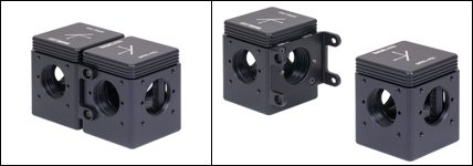
Two DFM1-P01 Beam Turning Cubes Connected Using the C4W-CC Cage Cube Connector
- Connect Two Beam Turning, Fluorescence Filter, or Beamspliter Cubes Side by Side
- Remove and Interchange Cube Inserts while the Cube Bases are Connected
- Connectors Available for 30 mm Cage Cubes with Ø1" or Ø32 mm Ports:
- DFM32-CC Cube Connector is Compatible with the DFM32 Series Bases
- C4W-CC Cube Connector is Compatible with the DFM1 Series Bases, Fiber Optic Filter Cubes, C4W, and C6WR Cage Cubes
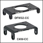
The DFM32-CC and C4W-CC Cage Cube Connectors allows two kinematic beam turning, fluorescence filter, or beamsplitter cubes to be connected together as shown in the image to the right. Two pins on the DFM32-CC connector are accepted by drilled holes on either side of the SM30-threaded (M30.5 x 0.5) ports located on each face of the DFM32 series base cubes to maintain alignment. The two pins on the DFM1-CC connector are accepted by drilled holes on either side of the SM1-threaded (1.035"-40) ports on the DFM1 series base cubes, Fiber Optic Filter Cubes, C4W, and C6WR Cage Cubes faces to maintain alignment. Cube inserts can still be removed and inserted while the cube bases are connected.
The DFM32-CC and C4W-CC connector hardware includes 4 flat head and 4 buttonhead #4-40 screws that can be secured with the included 5/64" hex key.
 Products Home


 Zoom
Zoom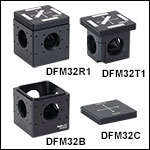
 30 mm Cage Cubes for Fluorescence Filter Sets