Kinematic Mounts for 60 mm Cage Systems
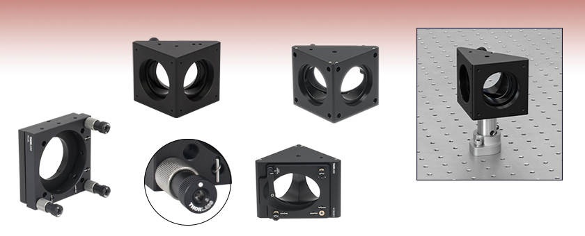
- Compatible with 60 mm Cage Systems
- Mount 2" (50.8 mm) Circular or Elliptical Optics
- Post Mountable
Anti-Drift
Locking Collar
KCB2
Tapped Cage Rod Holes
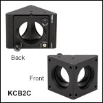
KCB2C
Smooth Cage Rod Bores
KCB2EC
Right-Angle Mount for Elliptical Mirrors
KC2L
Ø2" (Ø50.8 mm) Smooth
Bore in Front Plate
Application Idea
Using an RBP2 Pin-Aligned, Clamping Post Base and KCB2 Mount to Align a Laser Above the Holes in an Optical Table

Please Wait
| Alternative Size Options |
|---|
| 16 mm Kinematic Cage Mounts |
| 30 mm Kinematic Cage Mounts |
| 30 mm Right-Angle Kinematic Cage Mounts |
| 60 mm Kinematic Cage Mounts |
Features
- Kinematic Mounts for 2" (50.8 mm) Circular and Elliptical Optics
- Compatible with 60 mm Cage System
Thorlabs' Kinematic Mounts for 60 mm Cage Systems are designed to allow the functions of a kinematic optic mount to be easily integrated into our 60 mm cage system. These mounts are designed for use with 2" (50.8 mm) optics, including both round and elliptical mirrors. The KC2L(/M) and KC2T(/M) mounts are designed to mount round optics on the optical axis of a cage system, while the KCB2(/M), KCB2C(/M), and KCB2EC(/M) mounts are designed to mount optics at a 45° angle. The KCB2(/M) mount is equipped with tapped holes to accommodate ER cage rods. By contrast, the KCB2C(/M) and KCB2EC(/M) mounts are equipped with smooth bore holes for cage rods, which are secured by setscrews using a 5/64" (2 mm) hex key or balldriver.
The RBP2(/M) Pin-Aligned, Clamping Post Base, available below, is designed to align the surface of a mirror mounted in a KCB2(/M), KCB2C(/M), KCB2E(/M), or KCB2EC(/M) Right-Angle Kinematic Mirror Mount above a hole in the optical table, simplifying the process of aligning a reflected laser beam over the table's threaded holes. To use this clamping base, the KCB2 series mount must be attached to a Ø1" or Ø25 mm Pillar Post.
Cage System Compatibility: Thorlabs' cage system provides a convenient way to construct large optomechanical systems with an established line of precision-machined building blocks designed for high flexibility and accurate alignment. Thorlabs offers 16 mm, 30 mm, and 60 mm cage systems designed for Ø1/2", Ø1", and Ø2" optical components, respectively. See the “Cage Overview” tab for a full definition of this widely adapted construction standard. The parts on this page are compatible with our 60 mm cage system and utilize Ø6 mm ER cage rods.
Cage System Overview
The Cage Assembly System provides a convenient way to construct large optomechanical systems with an established line of precision-machined building blocks designed for high flexibility and accurate alignment.
16 mm, 30 mm, and 60 mm Cage System Standards
Thorlabs offers three standards defined by the center-to-center spacing of the cage assembly rods (see image below). The 16 mm cage, 30 mm cage, and 60 mm cage standards are designed to accommodate Ø1/2", Ø1", and Ø2" optics, respectively. Specialized cage plates that allow smaller optics to be directly inserted into our larger cage systems are also available.
Standard Threads
The flexibility of our Cage Assembly System stems from well-defined mounting and thread standards designed to directly interface with a wide range of specialized products. The three most prevalent thread standards are our SM05 Series (0.535"-40 thread), SM1 Series (1.035"-40 thread), and SM2 Series (2.035"-40 thread), all of which were defined to house the industry's most common optic sizes. Essential building blocks, such as our popular lens tubes, directly interface to these standards.

An example of the standard cage plate measurements determining cage system compatibility.
| Standard Cage System Measurements | |||
|---|---|---|---|
| Cage System | 16 mm | 30 mm | 60 mm |
| Thread Series | SM05 | SM1 | SM2 |
| Rod to Rod Spacing | 16 mm (0.63") | 30 mm (1.18") | 60 mm (2.36") |
| Total Length | 25 mm (0.98") | 41 mm (1.60") | 71.1 mm (2.80") |
| Cage Components | ||
|---|---|---|
| Cage Rods | 16 mm | These rods are used to connect cage plates, optic mounts, and other components in the cage system. The SR Series Cage Rods are compatible with our 16 mm cage systems, while the 30 mm and 60 mm cage systems use ER Series Cage Rods. |
| 30 mm | ||
| 60 mm | ||
| Cage Plates | 16 mm | These serve as the basic building blocks for a cage system. They may have SM-threaded central bores, smooth bores sized for industry standard optics or to accommodate the outer profile of our SM Series Lens Tubes, or specialized bores for other components such as our FiberPorts. |
| 30 mm | ||
| 60 mm | ||
| Optic Mounts | 16 mm | Thorlabs offers fixed, kinematic, rotation, and translation mounts specifically designed for our Cage Systems. |
| 30 mm | ||
| 60 mm | ||
| Cage Cubes | 16 mm | These cubes are useful for housing larger optical components, such as prisms or mirrors, or optics that need to sit at an angle to the beam path, such as beamsplitters. Our cage cubes are available empty or with pre-mounted optics. |
| 30 mm | ||
| 60 mm | ||
| Replacement Setscrews | Replacement setscrews are offered for our 16 mm (SS4B013, SS4B025, and SS4B038) and 30 mm (SS4MS5 and SS4MS4) cage systems products. | |
| Post and Breadboard Mounts and Adapters | Mounting options for cage systems can be found on our Cage System Construction pages. Cage Systems can be mounted either parallel or perpendicular to the table surface. | |
| Size Adapters | Cage System Size Adapters can be used to integrate components from different cage system and threading standards. | |
| Specialized Components | Thorlabs also produces specialized cage components, such as Filter Wheels, a HeNe Laser Mount, and a FiberPort Cage Plate Adapter, allowing a wide range of our products to be integrated into cage-mounted optical systems. Explore our Cage Systems Visual Navigation Guide to see the full range of Thorlabs' cage components. | |
| Posted Comments: | |
Francesco Scazza
(posted 2024-04-04 08:18:31.693) Do you have any data regarding the stability of the KCB2 and KCB2C, with respect for instance to Polaris-K2 mounts? Thanks jdelia
(posted 2024-04-04 04:27:18.0) Thank you for contacting Thorlabs. I have emailed you directly to share the stability data we have taken for our right-angle kinematic mirror mounts in comparison to our Polaris mounts. user
(posted 2024-01-05 05:09:40.86) Could you specify the thread pitch of locking mechanism? jdelia
(posted 2024-01-05 09:50:23.0) Thank you for contacting Thorlabs. If you are referring to the locking collets on the adjusters, this part has 0.290"-40 internal threading to mate with the external 0.290"-40 threads at the end of the bushing. The bushing in turn has internal 3/16"-100 threads to mate with the adjuster screws. If you are referring to the four cage-rod locking screws, those are 4-40 threaded. HJ Jung
(posted 2023-11-01 17:40:35.067) Hi, we've used one of your fantastic products KC2/M for mounting and fine alignment of our lens. I recently found that we need more information on KC2/M for fine alignment, that the estimated tilting degree of the front plate per 1 turn of TPI 100 adjuster. Obviously it would depend on which adjuster we turned or the front plate tilt degree itself, but we need some at least crude estimated value on that. Could you specify the distance between the two contact points of adjuster and the front plate so we can calculate the arc tan value per turn? cdolbashian
(posted 2023-11-13 05:03:04.0) Thank you for reaching out to us with this inquiry. As there is a bit of ambiguity regarding which distances you are referring, I have contacted you directly in order to figure out exactly which dimension you are seeking. Nita Riccobono
(posted 2022-04-14 12:29:48.71) Dear Thorlabs Representative,
The KCB2EC is nice, but I have 1 suggestion: create a baseplate for this so that you can position the center of the mirror directly over a hole on an optical table or breadboard. Ideally this baseplate would have a threaded hole for a 1/4-20 screw (to a post) directly under the center of the face of the elliptical mirror. I hope this is clear; please feel free to contact me if it isn't.
I typically center my optical path over screw holes on an optical table or breadboard; it just makes things easier to align, especially if there are bends in it. This method works fine with typical mounts because the screw hole for the post & post holder are centered beneath the center of the lens or mirror. Obviously this is not the case with this mount in its current configuration, and eyeballing it just isn't that precise.
Thank you!
Best regards,
Nita jdelia
(posted 2022-04-20 10:19:43.0) Thank you for contacting Thorlabs. I have forwarded your feedback along to our internal suggestion forum. In the meantime, I have contacted you directly regarding potential alternative solutions. Oliver Paxton
(posted 2021-09-26 22:40:28.67) Good Afternoon,
Throughout my PhD, our lab has been an avid user of Thorlabs products for our the optical measurement systems for experiments. Two of our most used products are the KC2/M and the KM200CP/M. The former can be adjusted about the mounting axis, which is fantastic for fine alignment of optics as it insures the centre of the mirror is always aligned to the mounting axis. While the latter is able to be mounted to frames and aligned relatively to other mirrors in the system.
If these two products could be combined into one - a single mirror mount which has fine adjustment about the mounting axis, as well as being able to connect to other mirrors in the system and use alignment plates - that would solve all alignment issues we run into during setup and experimental campaigns.
Thank you for taking the time to read my comments.
Kind Regards,
Oliver Paxton
oliver.paxton@uq.net.au YLohia
(posted 2021-10-14 05:29:26.0) Hello Oliver, thank you for your feedback. We will consider adding such a product to our catalog in the future. In the meantime, perhaps you can try using the KMCP Kinematic Mount Centering Plate
to position the optic face in-line with the post's rotation axis? ericb
(posted 2017-05-23 12:42:34.083) Hi, I just ordered two of these to be connected, via cage rods, to a cube LC6W. I noticed that when the cage rods screwed into the cube, and then put into the pockets of this mount they do not quite make an even inch distance. In fact the rod ends at the surface, but does not go into the hole. I expect that I will have to machine off a longer cage rod to make it work. However, if you have an easier solution to this, I'm all ears.
Thanks,
Eric nbayconich
(posted 2017-06-08 05:13:56.0) Thank you for contacting Thorlabs. I will reach out to you directly about your application. hobbs
(posted 2015-05-07 12:12:36.573) One important dimension is missing--what's the axial distance from flange to flange for light bouncing off the centre of the mirror? Looks like about 75 mm, but an exact distance would be helpful in assembling systems. cdaly
(posted 2015-05-11 08:44:55.0) Response from Chris at Thorlabs: With the beam traveling along the central axis of the 60mm cage on each side of the KCB2, the mirror would be positioned in such a way that the optical path length through the cube would be 3"(76.2mm). |

- Mounts Ø2" (Ø50.8 mm) Optics Along the Optical Axis of a 60 mm Cage System
- Through Holes for ER Cage Rods
- Provides ±3° Kinematic Tip and Tilt Adjustment
- KC2L(/M): Secures Optics with a Nylon-Tipped Setscrew
- KC2T(/M): SM2-Threads for Mounting Optics, Includes Two SM2RR Retaining Rings
- Post Mountable: Three 8-32 (M4) Tapped Holes
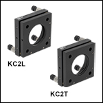
Our KC2L(/M) and KC2T(/M) Mounts provide kinematic tip and tilt adjustment of a Ø2" (Ø50.8 mm) optic. The KC2L(/M) includes a nylon-tipped setscrew to secure optics using a 5/64" (2 mm) hex key or balldriver. In contrast, the KC2-T(/M) is SM2-threaded and includes two SM2RR retaining rings to secure optics. Each mount has four through holes compatible with our ER Cage Rods and includes four setscrews to lock them into place using a 5/64" (2.0 mm) hex key or balldriver.
The KC2L(/M) and KC2T(/M) Kinematic Mounts offer three 100 TPI (Threads Per Inch) adjustment screws for smooth, high-resolution movement. Each adjuster is independently locking, and has a collet that can be tightened without causing the position of the adjuster to drift. The rugged mechanical design provides excellent stability when mounted in a cage system or on a post. Both the front and rear plates have been machined with four clearance holes designed for direct compatibility with our 60 mm cage system standards. The rear plate provides locking setscrews to clamp to cage rods for secure positioning. The cage rod holes in the front plate are sufficiently oversized to allow ±3º tip and tilt without interference with the rods.
The KC2L(/M) is designed for thicker optics with a 0.12" (3.0 mm) minimum thickness, while the KC2T(/M) is capable of mounting thin optics not exceeding 0.2" (5.0 mm) thick.

- Mounts Ø2" (Ø50.8 mm) Optics at a 45° Angle to the Optical Axis
- Eight 4-40 Tapped Holes for ER Cage Rods
- Provides ±4º Kinematic Tip and Tilt Adjustment
- 60 mm Cage System and SM2 (2.035"-40) Compatible
- Post Mountable:
The KCB2(/M) Right-Angle Kinematic Cage Mount provides kinematic tip and tilt adjustment of a Ø2" (Ø50.8 mm) optic held in a mounting plate with a mean horizontal position at a 45° angle. The ports are equipped with SM2-threaded (2.035"-40) bores. The KCB2(/M) has eight 4-40 tapped holes spaced to mate with our 60 mm cage systems. ERSCB ER Rod Adapters are necessary to effectively connect, adjust, and lock two of these right angle cage mounts together within the cage system. The ±4° kinematic tip and tilt adjustment plate is actuated with three 100 TPI (Threads per Inch) adjustment screws for smooth, high-resolution movement. Two of these adjusters include removable knobs, while the third must be tuned with a 5/64" (2 mm) hex key or balldriver.
A nylon-tipped setscrew is used to secure Ø2" (Ø50.8 mm) optics using a 5/64" (2 mm) hex key or balldriver via the mounts' rear-loading, double-bored hole. The rear loading design does not limit the maximum thickness of the mounted optic and the mounted optic remains accessible even after the mount is fitted with cage rods or lens tubes. The minimum thickness for optics that can be secured by these mounts is 0.24" (6 mm).

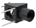
Click to Enlarge
KCB2C Mount with an Attached SM2L20 Lens Tube. The Mount Holds a BB2-E02 Broadband Dielectric Mirror.
- Mounts Ø2" (Ø50.8 mm) Optics at a 45° Angle to the Optical Axis
- Eight 0.20" (4.95 mm) Deep Smooth Bore Holes for ER Cage Rods
- Provides ±4º Kinematic Tip and Tilt Adjustment
- 60 mm Cage System and SM2 (2.035"-40) Compatible
- Post Mountable:
The KCB2C(/M) Right-Angle Kinematic Cage Mount provides kinematic tip and tilt adjustment of a Ø2" (Ø50.8 mm) optic held in a mounting plate with a mean horizontal position at a 45° angle. The ports are equipped with SM2-threaded (2.035"-40) bores and smooth bore holes spaced to mate with our 60 mm cage system standard. The cage rods are secured by setscrews using a 5/64" (2 mm) hex key or balldriver. This design allows multiple 60 mm cage components to be directly interfaced without the need for ERSCB ER Rod Adapters. The ±4° kinematic tip and tilt adjustment plate is actuated with three 100 TPI (Threads per Inch) adjustment screws for smooth, high-resolution movement. Two of these adjusters include removable knobs, while the third must be tuned with a 5/64" (2 mm) hex key or balldriver.
A nylon-tipped setscrew is used to secure Ø2" (Ø50.8 mm) optics using a 5/64" (2 mm) hex key or balldriver via the mounts' rear-loading, double-bored hole. When used with transmissive optics, two clearance cuts around this hole provide a Ø1.26" (Ø32.0 mm) nominal clear aperture for any transmitted light. The rear loading design does not limit the maximum thickness of the mounted optic and the mounted optic remains accessible even after the mount is fitted with cage rods or lens tubes. The minimum thickness for optics that can be secured by these mounts is 0.24" (6 mm).

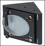
Click to Enlarge
The mirror is locked in place by a swing arm and nylon-tipped setscrew. The adjuster knobs feature side holes for fine adjustments.
- Mounts 2" (50.8 mm) Elliptical Optics at a 45° Angle to the Optical Axis
- Eight 0.195" (5.0 mm) Deep Smooth Bore Holes for ER Cage Rods
- Provides ±3º Kinematic Pitch and Yaw Adjustment
- Z-Axis Translation Using All Three Adjusters: ±0.12" (±3.0 mm)
- 60 mm Cage System and SM2 (2.035"-40) Compatible
- Post Mountable:
The KCB2EC(/M) Right-Angle Kinematic Cage Mount provides kinematic pitch and yaw adjustment of a 2" (50.8 mm) elliptical optic held in a mounting plate with a nominal horizontal position at a 45° angle. The ports are equipped with SM2-threaded (2.035"-40) bores and four 0.195" (5.0 mm) deep smooth bore holes spaced to mate with our 60 mm cage system standard.
The ±3° kinematic pitch and yaw adjustment plate is actuated with three 100 TPI (threads per inch) adjustment screws that provide angular resolution of 4.5 mrad/rev. The pitch and yaw adjusters include removable knobs with Ø5/64" (Ø2 mm) side holes for fine adjustments, while the third adjuster must be tuned with a 5/64" (2 mm) hex key or balldriver. While the optic face is nominally centered within the mount, the third adjuster can be used for fine tuning the position along the optical axis.
A nylon-tipped setscrew mounted on a swing arm is used to secure 2" (50.8 mm) elliptical optics using a 5/64" (2 mm) hex key or balldriver via the mount's rear-loading, double-bored hole. Note that the setscrew should only be finger tight to avoid distorting the optic. Please note that this mount is compatible only with 2" elliptical optics that are 0.47" (12 mm) thick. Our selection of dielectric and metallic elliptical mirrors are compatible with this mount.

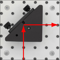
Click to Enlarge Alignment of Laser Beam Along Holes of Optical Table Using an RBP2 Post Base
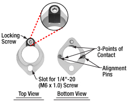
Click to Enlarge
Top and Bottom View of the RBP2 Post Base
- Ideal for Aligning a Laser Beam Along the Threaded Holes of an Optical Table
- Compatible with Imperial and Metric Optical Tables and Ø1" or Ø25 mm Pillar Posts
- Alignment Pins and Attachment Screw Position the Front Surface of the Mirror in a KCB2 Series Mount Above a Hole in the Table
- Post Rotates Freely When Locking Screw is Loosened
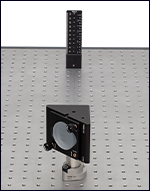
Click to Enlarge Using a BHM6 Ruler and RBP2 Base to Align a KCB2 Mount
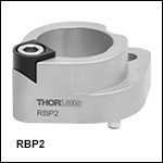
The RBP2(/M) Pin-Aligned, Clamping Post Base is designed to simplify aligning a laser beam over the threaded holes in an imperial or metric optical table by holding the front surface of a mirror mounted in a KCB2(/M), KCB2C(/M), or KCB2EC(/M) Right-Angle Kinematic Mirror Mount above a hole in the table. The clamping post base accepts Ø1" (Ø25 mm) Pillar Posts, to which the right-angle mirror mount can be connected as shown in the image to the left; note that the base does not accept pedestal posts. Alignment pins on the bottom of the RBP2(/M) post base fit into the holes on an optical table, which sets the mount in the correct position, while a 1/4"-20 (M6) cap screw and washer (not included) secure the clamp to the table. The body of the clamp is made of stainless steel, with an additional anodized aluminum piece that works with the locking screw to lock the post to the clamp.
Once the RBP2(/M) is attached to the table, the angle of the post can be set so that the mirror sends the beam along the general direction of the holes in the table by aligning the center of the back of the mount over the locking screw side of the clamp, as shown in the image above and to the right. To secure the post in place, tighten the locking screw with a 3/16” (5 mm) hex key or balldriver. The post clamping mechanism uses three points of contact for stable mounting (see the image to the upper right). The knobs on the mirror mount can then be used for further precise alignment of the beam. We recommend the BHM6 Magnetic Beam Height Ruler with Dowel Pins as an ideal tool for aligning a laser with a table's hole pattern using the RBP2(/M) post bases, as it places a series of alignment holes at different heights above two threaded holes in the table (see the image to the left).
For our complete selection of Pin-Aligned, Clamping Post Bases, see the full web presentation.
 Products Home


 Zoom
Zoom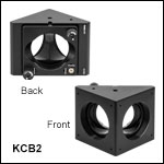

 Kinematic Mirror Mounts