 Products Home / Active Optical Devices / Fast Modulator and Attenuator for High-Power, Femtosecond Lasers
Fast Modulator and Attenuator for High-Power, Femtosecond Lasers

- Operating Wavelength Covers Full Range of Yb-Based Lasers: 1020 - 1080 nm
- Modulation and Attenuation for Up to 40 W, 40 μJ Lasers
- Micromachining and Microscopy Beam Blanking
- Built-in Angular Dispersion Compensation
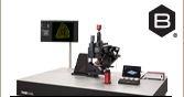
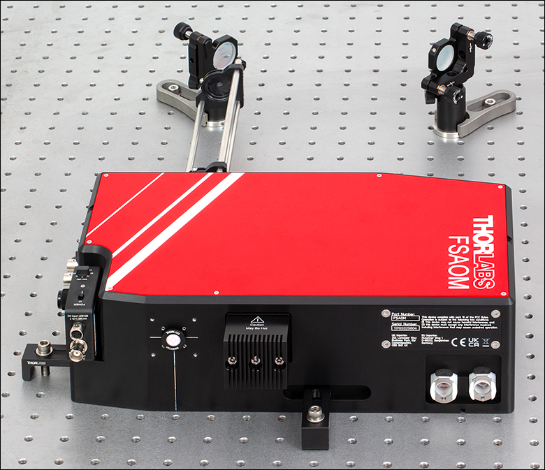
The FSAOM unit can be aligned with the aid of the included cage rods, irises, and alignment disk at a beam height of 2.50".
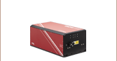
FSAOM
Fast Modulator and Attenuator for High-Power, Femtosecond Lasers, 1020 - 1080 nm


Please Wait
Click to Enlarge
The typical transmission for the FSAOM modulator as a function of the voltage to drive the AOM is shown. The diagnostic voltage is the output from the attached photodetector. Transmission is also affected by factors such as optical power, wavelength, and the spot size of the beam, see the Graphs tab for additional performance graphs.
Applications
- Fast Power Modulation of NIR Femtosecond Lasers
- Two-Photon Photostimulation
- Femtosecond Micromachining
- Galvo-Galvo or Galvo-Resonant Scanning
- Edge, Frame, Fly-Back Blanking
- Region of Interest Selection
Click to Enlarge
30 mm cage system rods (Item # ER8-P4) and two irises (Item # CP20D) are provided along with an alignment disk (Item # VRC4SM05) to aid alignment. The unit is secured to the optical table with the included CL5A clamps. Mirrors, posts, and clamping forks are sold separately.
Features
- High Damage Threshold Material and Optics
- Up to 40 W Average Power and 40 μJ Pulse Energy
- Quartz AOM
- Low Group Delay Dispersion (1023 fs2)
- DC Power Attenuation and High-Speed Modulation Up to 2 MHz
- <200 ns On/Off Time
- Uses 1st Order Diffracted Beam for 1000:1 Contrast Ratio
- Broadband Operation
- 1020 - 1080 nm Operating Range
- Pockels Cell Alternative
- Analog and Digital Control of Optical Output
- Compatible with ThorImage®LS and ScanImage Software
- PDA20CS2 Photodetector Included for Monitoring/Calibrating Output Power
- Water Cooled, Compatible with the LK220 Liquid Chiller
- Vertical Alignment Marks Centered on the Input and Output Ports
- FSAOMB Riser (Sold Separately Below) Increases Beam Input Height to 4.75"
Thorlabs' FSAOM Modulator and Attenuator provides high-speed intensity modulation and beam attenuation for high-power lasers with operating wavelengths from 1020 - 1080 nm, ideal for use with our Ytterbium Femtosecond Fiber Lasers or other Yb-based lasers used in multiphoton imaging or micromachining. The unit features an analog and digitally controlled AOM capable of high contrast (>1000:1) modulation, an operating frequency up to 2 MHz, and >80% (at 1030 nm) transmission efficiency. This unidirectional device is designed for a collimated, 1.5 to 3 mm 1/e2 diameter, vertically polarized input beam with up to 40 W of optical power and up to 40 µJ of pulse energy, enabling use with popular 1 µm wavelength high-pulse-energy lasers.
Transmission is controlled by a 0 to 5 V analog input, as shown in the graph to the upper right. A 0 or 5 V digital signal can also be used to toggle the transmission on or off, respectively. The AOM responds quickly to these voltage changes and the time for the transmission to go from 10% to 90% and vice versa is less than 200 ns. Please see the Rise/Fall Time tab for more detail on the AOM output response to analog and digital inputs. These voltages can be easily generated by off-the-shelf DAQ hardware or other electronics. To aid in setup and ease of use, the FSAOM device also includes an "AOM always-on" mode that sets the AOM to continuous DC operation (indicated by the "AOM ON" LED on the front panel). The device supports continuous DC operation as well as modulation frequencies up to 2 MHz, making it ideal for imaging applications such as fly-back blanking or region of interest (ROI) selection.
Ideal for Photoactivation and Two-Photon Fluorescence Applications
The modulator is suitable for many applications including two-photon fluorescence microscopy and photoactivation. Both of these techniques require fast laser power modulation of ultrafast NIR laser pulses, such as those generated by the Ytterbium Femtosecond Fiber Lasers, to limit sample exposure during imaging and reduce thermally induced damage. Furthermore, the FSAOM device is equipped with a specially designed prism to compensate the wavelength dependent angular dispersion induced by diffraction-based modulators such as AOMs, which can affect the focal spot quality. See the Beam Quality tab for details.
Replaceable Photodetector
An internal beam sampler directs a small portion (~1%) of the modulated beam to a separate output port where a photodetector can be used to monitor the transmission. If desired, the included, pre-installed PDA20CS2 detector can be easily removed and replaced with a user-supplied detector; to do so, loosen the 8-32 mounting screw located in the slot below the detector using a 9/64" hex key.
Active Water Cooling
The AOM requires cooling during operation; a liquid chiller, such as the LK220 Thermoelectric Liquid Chiller (not included), must be installed and running water cooled to 20 °C through the unit before enabling the AOM. The FSAOM unit's electrical system includes a thermal interlock circuit to disable and safeguard the AOM if it exceeds it’s operational temperature limit. Water line connections are provided on the FSAOM unit's side panel to mate to the included two QVF6 valved in-line coupling inserts and HPU6 polyurethane hose, see the Panels tab for coupling location and check the manual for setup instructions.
Housing and Mounting Features
The input, output, and photodetector ports of the laser power modulator have internal SM05 (0.535"-40) threading which can be used to install external SM05-threaded components. The input and output ports also feature 4-40 threaded holes for compatibility with our 30 mm cage systems. To aid in alignment, four ER8 8" cage assembly rods are provided along with two CP20D cage mounted irises and a VRC4SM05 alignment disk. Follow the alignment strategy in the manual to achieve full transmission through the device using the included cage mounted irises and alignment disk. See the photo to the right for an example alignment setup.
Four slots in the enclosure allow the modulator to be mounted directly to an optical table with table clamps, such as our CL5A clamps (three are included), resulting in a beam height of 2.50". The base also includes four M6 mounting holes for attaching the FSAOMB riser (sold below) to give a beam height of 4.75", allowing direct alignment with our Ytterbium Femtosecond Fiber Lasers.
The unit is shipped with a DS24 24 V power supply with a KPJX-3S connector for the modulator, as well as a LDS12B ±12 V supply for the photodetector. A region-specific power cord is shipped with the power supplies based on your location.
Femtosecond Acousto-Optic Modulator Housing Dimensions
| Item # | FSAOM |
|---|---|
| Contrast Ratio | >1000:1 |
| Operating Range | 1020 - 1080 nm |
| Included Photodetector | Item # PDA20CS2 |
| Input Polarization | Vertical Linear |
| Output Polarization | Vertical Linear |
| Rise/Fall Time | <200 ns |
| Modulation Frequencya | 0 - 2 MHz |
| Modulation Voltage | 0 - 5 V |
| Input Impedance | 1.5 kΩ |
| Transmission (at 1030 nm) | >80% |
| Max Input Pulse Energyb | 40 µJ |
| Max Input Optical Powerb | 40 W |
| Input Spatial Mode Rangec | Ø1.5 - 3 mm |
| Group Delay Dispersion | 1023 fs2 |
| Power Supply (Included) | Item # DS24, 24 V, 160 W |
| Power Connector | KPJX-3S Female Connector |
| Operating Temperature | 15 - 30 °C |
| Operating Humidity | 20 - 60% |
| Storage Temperature | -25 - 70 °C |
| Required Chiller Cooling Capacity | 100 W |
| Housing Dimensions (L x W x H)d | 12.60" x 6.89" x 3.77" (320.0 mm x 175.0 mm x 95.9 mm) |
| Dimensions with FSAOMB Riser (Sold Separately) (L x W x H)e |
12.60" x 6.89" x 6.02" (320.0 mm x 175.0 mm x 152.9mm) |
- 11% Reduction in Modulation Depth at 3 MHz
- Rep Rate: 1 MHz, FWHM: 250 fs, 2 mm 1/e2 Beam Diameter
- 1/e2 Beam Diameter, >Ø3 mm Reduces the Transmission Efficiency
- Beam input height is 2.50". For further details, please refer to the mechanical drawing found by clicking the red Docs (
 ) icon below.
 - Beam input height increases to 4.75" with the FSAOMB Riser.
The graphs below show the typical transmission through the FSAOM modulator as a function of driving voltage, optical input power, wavelength, and spot size. The modulation performance when the AOM is driven at 1, 2, and 3 MHz is also shown.

Click to Enlarge
Click Here for Data
The typical transmission through the FSAOM modulator is shown as a function of the average optical input power, indicating no evidence of thermal effects at high power.
Click to Enlarge
Click Here for Data
The typical transmission through the FSAOM modulator with an optical input power of 39.6 W (1030 nm) is shown as a function of the voltage to drive the AOM. The diagnostic voltage is the output from the attached photodetector.

Click to Enlarge
Click Here for Data
The typical transmission is shown as a function of the spot size (1/e2 beam diameter) at the input of the FSAOM modulator. The blue highlighted region from ∅1.5 to 3 mm represents the accepted range; >3 mm reduces transmission efficiency.

Click to Enlarge
Click Here for Data
The typical transmission through the FSAOM modulator is shown as a function of wavelength. The blue highlighted region from 1020 - 1080 nm represents the operational wavelength range.

Click to Enlarge
Click Here for Data
The contrast ratio of the modulated light remains stable within repetition rates ranging from 0 to 2 MHz. However, beyond 2 MHz, the contrast ratio begins to decrease. For instance, at 3 MHz, the contrast ratio reduces to 10:1.
Click to Enlarge
As long as the digital input is 0 V, the AOM transmission follows the analog signal input as shown above. Applying 5 V on the digital input turns off the transmission.
Operating Mode Control Diagram
The diagram on the right shows how the Analog and Digital input signals correspond to the laser transmission output from the FSAOM unit.
- Analog: Laser simply follows the analog signal. The device can be fully operated by applying only an analog signal to the analog channel:
- 0 V → 0 % Laser Out
- 0 - 5 V → See Typical Transmission Graph in the Graphs Tab
- 5 V → 100 % Laser Out
- Digital: The user adds 0 - 5 V (for different levels of attenuation) to the analog input (via output of DAQ, or with a power supply), and then applies their digital signal to the digital channel:
- TTL Lo (0 V) → Follow Analog
- TTL Hi (5 V) → 0% Laser Out
Note: When at 100% output, ~80% of the input power is transmitted. See the Graphs tab for details
The graphs below show how the Analog and Digital control signals impact the AOM operation and resultant laser transmission.
Analog Input
An external analog input of 0 - 5 V controls the optical output of the modulator from 0 - 100%. When a 0 - 5 V analog signal is applied to the analog input, the optical output will follow this signal after an initial delay time indicated in green on the graphs below. The rise time is the time interval the optical output increases from 10% to 90% of the maximum transmission, while the fall time is the time interval the optical output decreases from 90% to 10% of the maximum transmission. A beam with a 2 mm 1/e2 beam diameter was sent to the FSAOM device's input port for these measurements.
Click to Enlarge
Click Here for Data
When a 5 V signal on the analog input is then set to 0 V, the optical output will drop after an initial delay from 90% of the applied signal to 90% of the maximum transmission. The fall time is shown by the dashed line interval and is the time for the optical output to decrease from 90% to 10% of the maximum transmission.

Digital Input
An external digital input of 0 or 5 V combined with the external analog input of 0 - 5 V controls the optical output of the modulator. The graphs below show the rise and fall times of the optical output when a 0 or 5 V signal is applied to the digital input, while 5 V is present on the analog input. A beam with a 2 mm 1/e2 beam diameter was sent to the FSAOM device's input port for these measurements.

Click to Enlarge
Click Here for Data
The digital fall time is shown by the dashed line interval and is the time it takes the optical output to go from 90% to 10% of its maximum transmission when a 5 V signal exists on the analog input of the AOM and the digital input is switched from 0 to 5 V, disabling transmission.
Click to Enlarge
Click Here for Data
The digital rise time is shown by the dashed line interval and is the time it takes the optical output to increase from 10% to 90% of its maximum transmission when a 5 V signal initially exists on the analog and digital inputs of the AOM and the digital input is then set to 0 V, enabling transmission.

Click to Enlarge
The picture above illustrates the beam path through the FSAOM unit. The inner components of the unit are shown only to aid in understanding; the housing cover should not be removed and the internal optics should not be adjusted.
Inside the FSAOM Device
The internal design of the FSAOM unit incorporates the optics needed to shape and align a high-power femtosecond laser pulse with wavelength range from 1020 to 1080 nm through an AOM and output a modulated angular-dispersion compensated beam. The photo to the right illustrates the beam path through the device. Please note that housing cover should not be removed; there are no user-serviceable parts inside the device.
The FSAOM device accepts a 1.5 to 3 mm diameter vertically polarized beam (thick green line) at the input port. A UV Fused Silica Galilean beam reducer (Item # BE02-1064) matches the laser beam mode size of the active area of the AOM, where the beam is modulated and the 1st order diffracted beam separates from the 0th order undiffracted beam. The wavelength dependent angular dispersion in the 1st order diffracted beam is compensated by the specially designed prism. The path of the 0th order beam is shown by the dashed line as it separates from the diffracted beam and is sent to the beam dump. A portion (~1%) of the 1st order beam is picked off for diagnostic use, before exiting the device.
In designing Thorlabs' FSAOM Acousto-Optic Modulator, reliably maintaining output beam quality was a priority. This is because a beam's mode quality is important for a wide range of applications, including micromachining and multiphoton photostimulation. Beam quality was tested by using beams generated by Thorlabs' SLD1050P-A60 Superluminescent Diode Laser and TC12APC-1064 Collimator and measuring the beam profiles.
Beam Profiles
Diffraction-based modulators such as AOMs introduce wavelength dependent angular dispersion that can affect focal spot and image quality, therefore the FSAOM device is equipped with an angular dispersion compensating prism. The picture on the left shows the beam profiles taken at the focus of a 100 mm lens in front of the device output without (left profile) and with (right profile) an angular dispersion compensating prism installed. The inclusion of the compensation prism eliminates angular dispersion or spatial chirp, resulting in a circular output beam even for broad-bandwidth input lasers.
The FSAOM device houses all the optics needed to resize and align the beam through the AOM and emerge with minimal loss of quality at 1/2 the diameter, as shown in the image on the right. Beam quality measurements along the x and y-axis before entering the device yield M2x = 1.01 and M2y = 1.03, and after exiting the device are M2x = 1.06 and M2y = 1.06.
The FSAOM device is designed to maintain the beam location, direction, and vertical polarization of the input beam, so it can be added to existing optical setups without requiring a complete re-routing of the downstream optical path. The BE02-1064 UVFS 2x Beam Expander can be used to bring the output mode diameter back to its original size.
Input and Output Beam Profiles

Click to Enlarge
Left Beam Profile: A beam with a 2 mm 1/e2 beam diameter enters the FSAOM unit. Right Beam Profile: The beam exits the FSAOM unit with 1/2 the diameter.
Beam Profile Without vs With Compensating Prism

Click to Enlarge
Left Beam Profile: The broad-bandwidth beam is elliptical due to the uncompensated angular dispersion of the AOM, also known as spatial chirp. Right Beam Profile: The inclusion of the compensation prism eliminates the angular dispersion, or spatial chirp, and the resulting ellipticity.
Femtosecond Acousto-Optic Modulator Front Panel

Click to Enlarge
| Front Panel of the FSAOM Unit | |
|---|---|
| Callout | Description |
| 1 | Rotary Knob, Source/ Enable |
| 2 | Digital In (BNC), 5 V, High-Z |
| 3 | Analog In (BNC), 0 - 5 V, 1.5 kΩ |
| 4 | AC Power Cord (Item # DS24) Connector |
| 5 | Input Optical Specifications |
| 6 | Error / Reset Button |
| 7 | AC Power On/Off Switch |
| 8 | Device Status Indicator |
| 9 | Output Monitor, PDA20CS2 InGaAs Photodetector |

Click to Enlarge
| Input Side Panel of the FSAOM Unit | |
|---|---|
| Callout | Description |
| 1 | Beam Entrance Aperture |
| 2 | Mounting Location for 30 mm Cage System |
| 3 | CL5A Clamp Location |
Femtosecond Acousto-Optic Modulator Side Panels

Click to Enlarge
| Output Side Panel of the FSAOM Unit | |
|---|---|
| Callout | Description |
| 1a | Water Line Quick-Disconnect Couplings |
| 2 | CL5A Clamp Location |
| 3 | Mounting Location for 30 mm Cage System |
| 4 | Beam Exit Aperture |
| 5 | Beam Dump |
| 6 | Serial Plate |
FSAOM Modulator Connections
BNC Female, Analog Modulation Signal Input
Analog Signal Input is 0 - 5 V, 1.5 kΩ
BNC Female, Digital Modulation Signal Input
Digital Signal Input is 5 V TTL, High-Z
KPJX-3S Connector, Female Power IN*

*For the Included DS24 Power Supply
PDA20CS2 Photodetector Connections
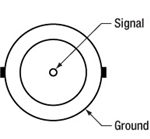
BNC Female Output (Photodetector)
0 - 10 V Output
Male (Power Cable)*
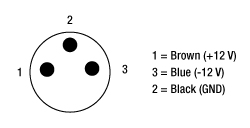
*For the Included LDS12B Power Supply
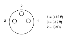
Female Power IN (Photodetector)
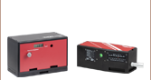
Components Included with the FSAOM Laser Power Modulator
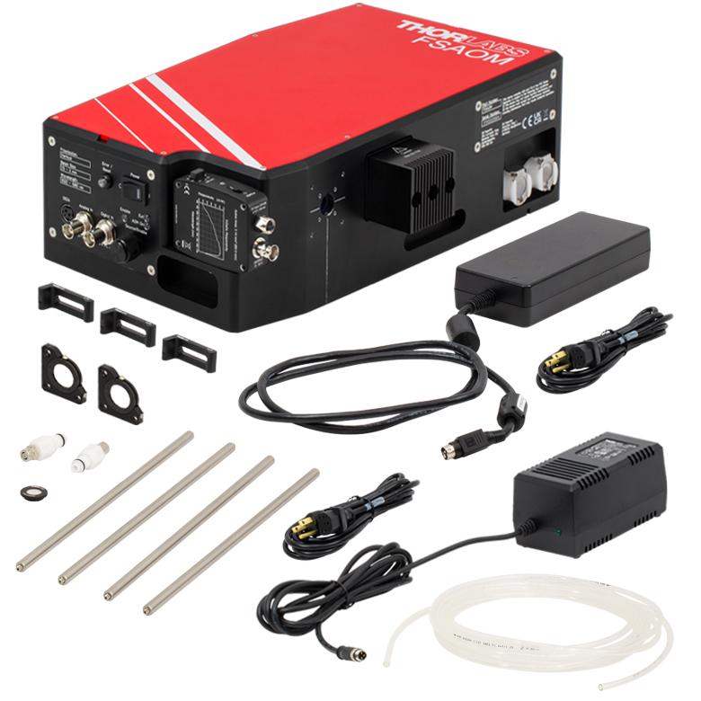
Click to Enlarge
Components Shipped with the FSAOM Laser Power Modulator
- Laser Power Modulator with attached PDA20CS2 InGaAs Photodetector
- DS24 24 VDC Power Supply
- LDS12B ±12 VDC Power Supply
- HPU6 5 m Polyurethane Hose
- QVF6 Hose Valved In-Line Coupling Insert (Qty 2)
- CP20D 30 mm Cage Mounted Iris (Qty 2)
- ER8-P4 8" Cage Assembly Rod (Pack of Four)
- CL5A Table Clamp (Qty 3)
- VRC4SM05 IR Alignment Disk
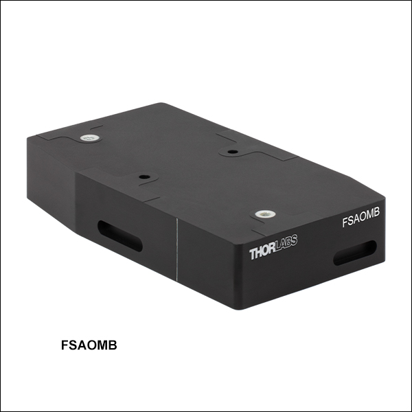
Components Included with the FSAOMB Riser

Click to Enlarge
Components Shipped with the FSAOMB Riser
- FSAOMB Riser
- M6 x 1.0 Screws (Qty 4)
| Posted Comments: | |
| No Comments Posted |

 Zoom
Zoom
Beam input specs are printed on the front panel. Note the beam diameter is reduced by half at the output, see the Beam Quality tab for details.
- Operating Wavelength Range from 1020 to 1080 nm
- DC Power Attenuation and High-Speed Modulation up to 2 MHz:
- <200 ns On/Off Time
- Uses 1st Order Diffracted Beam for 1000:1 Contrast Ratio
- High-Power Handling: Up to 40 W Optical Power and 40 μJ Pulse Energy
- >80% Transmission (at 1030 nm)
- Includes PDA20CS2 InGaAs Photodetector
- Compatible with the LK220 Liquid Chiller (Sold Separately)
Thorlabs' FSAOM Laser Power Modulator is a fully integrated acousto-optic modulator solution ideal for applications requiring high-speed modulation and variable attenuation of high-power femtosecond pulses with wavelength range from 1020 to 1080 nm. The unit incorporates all the optics needed to resize and align the beam into the AOM and includes an angular dispersion compensating prism on the output. The user needs only to align a collimated, vertically polarized, Ø1.5 - 3 mm diameter beam into the input port to achieve a modulating output that retains its beam quality. Note that the modulator is unidirectional and will not work properly if aligned in the opposite direction, see the FSAOM Design and Panels tab for details.
A chiller, such as the LK220 liquid chiller (not included), must be installed and running water cooled to 20 °C before aligning a beam into the device, please see the manual for installation instructions.

 Zoom
Zoom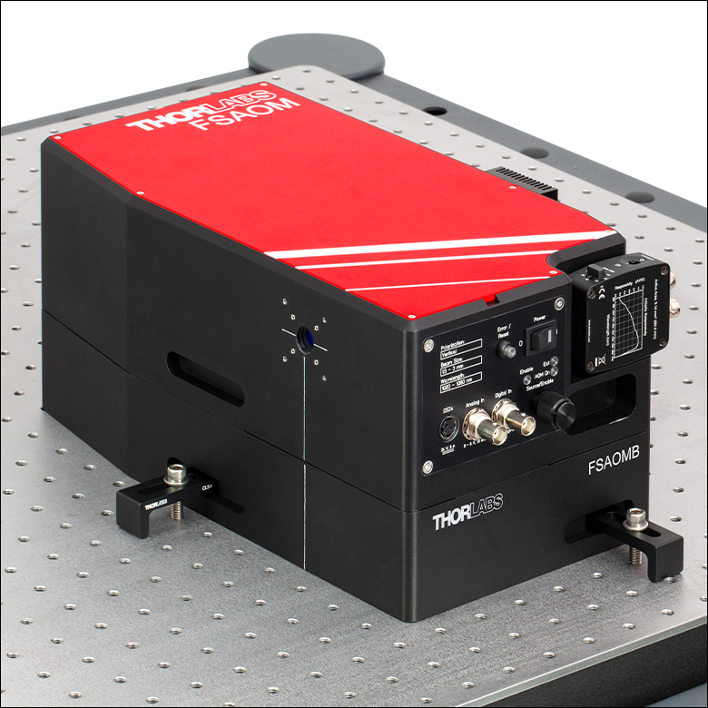
Click to Enlarge
FSAOMB Riser Attached to the FSAOM Unit
- Increase the Beam Input Height of the FSAOM Modulator to 4.75"
- Includes Four M6 Mounting Screws to Attach the FSAOM Modulator
- Four Slots for CL5A L-Shaped Table Clamps (3x Included with the FSAOM Unit)