PMMA Microlens Arrays

- Plano-Convex Lens Shape
- Rectangular Grid Arrangement of Microlenses
- Uncoated or AR Coated
- Mounted and Unmounted Versions
Application Idea
Use Microlens Arrays to transform a round collimated beam into a rectangular homogeneous spot.
See the Application tab for details.
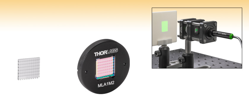
MLA1
Unmounted Uncoated PMMA Microlens Array
MLA1M2
Mounted AR Coated PMMA Microlens Array

Please Wait
| Unmounted Item # | MLA1 | MLA11 | MLA12 |
|---|---|---|---|
| Mounted Item # | MLA1M | MLA1M1 | MLA1M2 |
| Substrate Material (Click for Plot) |
PMMA | ||
| Effective Focal Length | 4.7 mm @ 850 nm | ||
| Lenslet Pitch | 1.0 mm x 1.4 mm | ||
| Single Lens Radius | 2.7 mm | ||
| AR Coating (Click for Plot) |
- | 420 - 700 nm | 650 - 1050 nm |
| Reflectance (Average) | - | <0.8%, 0° AOI | <0.8%, 0° AOI |
| Array Size and Type (Length x Height x Thickness) |
10.0 mm x 9.8 mm x 1.2 mm Rectangular Grid |
||
| Length and Height Tolerances (Unmounted Versions Only) |
±0.1 mm | ||
| Window Aperture (Mounted Versions Only) |
9.0 mm x 9.0 mm | ||
| Click on the red Document icon next to the item numbers below to access the Zemax file download. Our entire Zemax Catalog is also available. |
Features
- Polymethyl Methacrylate (PMMA) Substrate
- 10.0 mm x 9.8 mm High-Quality Microlens Array
- Available Unmounted or in a Ø1" Mount
- Offered Uncoated or Broadband AR Coated
- 420 - 700 nm with an AR Coating
- 650 - 1050 nm with an AR Coating
- Rectangular Grid Arrangement of Microlenses
- Arrays with 1.0 mm x 1.4 mm Lenslet Pitches
- 2.7 mm Single Lens Radius
- Ideal for Producing a Square Spot with a Flat Top Profile
These PMMA Microlens Arrays (MLAs) are available mounted or unmounted. MLAs are excellent for homogenizing and shaping light, yielding a flat top profile output or square spot patterns. PMMA has excellent UV resistance, filtering out UV light less than 300 nm. The microlenses have a plano-convex shape and are arranged in a 10.0 mm by 9.8 mm rectangular grid with a lens pitch of 1.0 mm by 1.4 mm. These can be used in fly's eye homogenizer configurations, where a round beam is transformed into a rectangular spot (see the Application tab for details). Alternatively, Thorlabs offers a line of Fly's Eye Homogenizer devices using these MLAs with 40 mm or 95 mm working distances.
For the mounted versions, the MLA is glued into a Ø1", 4.0 mm thick mount that is externally SM1-threaded (1.035"-40). The aperture of the lens window is 9.0 mm by 9.0 mm. The plate has slots that are compatible with a SPW602, SPW606, SPW801, or SPW909 spanner wrench. Their unmounted counterparts are most easily held using one of our cylindrical lens mounts, which are specifically designed to hold square or rectangular optics.
Please note that the Zemax file provided below is not the common sequential (SC) raytracing file which we typically provide, but the non-sequential (NSC) raytracing file. Be aware that the standard version of Zemax OpticStudio® does not support the NSC mode.
AR Coating Options
While our uncoated PMMA microlens arrays offer excellent performance, improved transmission can be gained by choosing a lens with an antireflective coating on both sides to reduce the surface reflections. Our broadband antireflection (BBAR) coatings provide <0.8% average reflectance over one of the following wavelength ranges: 420 - 700 nm or 650 - 1050 nm.
For microlens arrays that are ideal for use in custom-built Shack-Hartmann wavefront sensors, please visit the Fused Silica Microlens Arrays page.

Click to Enlarge
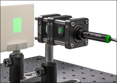
This fly's eye homogenizer can be used to transform a round Gaussian collimated beam into a rectangular homogeneous area.
 Click to Enlarge
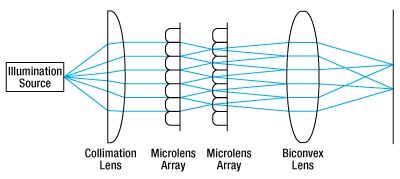
A Simplified Diagram of the Setup
Fly's Eye Homogenizer
There are multiple ways to homogenize the output of a light source. Microlens arrays (MLAs) used in a fly's eye homogenizer configuration transform a round collimated beam with a Gaussian profile into a rectangular homogeneous area. The size of the rectangle is defined by the size and pitch of the microlenses.
The application photo to the right shows one possible fly's eye homogenizer configuration mounted in a 30 mm cage system. The light source is a PL201 compact laser module fixed in an AD11F SM1-threaded adapter held in a CP33(/M) cage plate. Alternatively, other light sources can be used such as a fiber-coupled LED connected to a collimator or mounted LED with a collimation adapter. The light passes through the first of two MLAs held in CP6T cage plates. These cage plates are thin enough to hold the mounted MLAs and secure them with a retaining ring while allowing the user to place the MLAs as close as possible to each other to maximize the rectangular output size. The lensed side of the first MLA should face the source. It is key to accurately align the rotation of the MLAs relative to each other; there will be artifacts on screen otherwise. The light then passes through an LB1471 N-BK7 bi-convex lens to produce a rectangular 9 mm x 12 mm area on an EDU-VS2(/M) screen, as seen in the photo to the right. A similar setup can be produced using our Fly's Eye Homogenizer devices as seen here.
Please note that the output rectangle is only sharply defined at a specific distance from the focusing lens. The actual size of the rectangle can be adjusted by changing the distance between the two MLAs. Decreasing the distance will increase the size of the rectangle and increasing the distance will make the rectangle smaller. Smaller rectangle sizes can also be produced by using lenses with shorter focal lengths. A simplified diagram of the setup is shown on the bottom right.
In this example, the setup was mounted using Ø1/2" posts and post holders that were secured to an MB3045(/M) breadboard using clamping forks.
| Posted Comments: | |
Iveth Guatibonza
(posted 2024-07-23 17:13:17.35) I am also curious about the feasibility of using this microlens array for light field imaging. If it is possible, what would be the implications for imaging quality and performance? Thank you! Hong Wei
(posted 2024-05-13 16:31:14.9) Hi,
Under the application tab of MLA1M2, you recommended a layout that can produce an uniform rectangle projection of laser beam. You suggested using LB1471 lens with 50mm focal length. However, you didn't define the distance between each component. My understand is that the distance between two MLAs and the distance from the second MLA to the project lens LB1271 matters. Would you please provide that info?
Regards,
Hong jjadvani
(posted 2024-05-17 06:41:20.0) Dear Hong, thank you for contacting us! Application idea is based on Fly’s Eye Homogenizer. I will contact you directly to provide further support. Zhouyu Wang
(posted 2022-09-05 11:29:22.877) I wonder if this kind of microlens array could be used for imaging devices such as lightfield camera.We are looking for similar products for imaging purpose. mdiekmann
(posted 2022-09-05 10:45:42.0) Thank you for contacting us! A member of our local tech support team will reach out to you directly to discuss your application. ke wang
(posted 2021-09-29 12:13:30.187) 1. I want to know the damage threshold of MLA11 PMMA microlens array
my laser:
DPSS 532nm laser
power:300mw
working mode:CW
beam diameter:6-9mm soswald
(posted 2021-10-14 06:14:52.0) Dear Ke Wang,
thank you for your feedback. We have not formally tested the damage threshold for MLA11. I have reached out to you to discuss your application in more detail and provide further assistance. |
 Products Home


 PMMA Microlens Arrays