High-Pass Electrical Filters, BNC Feedthrough
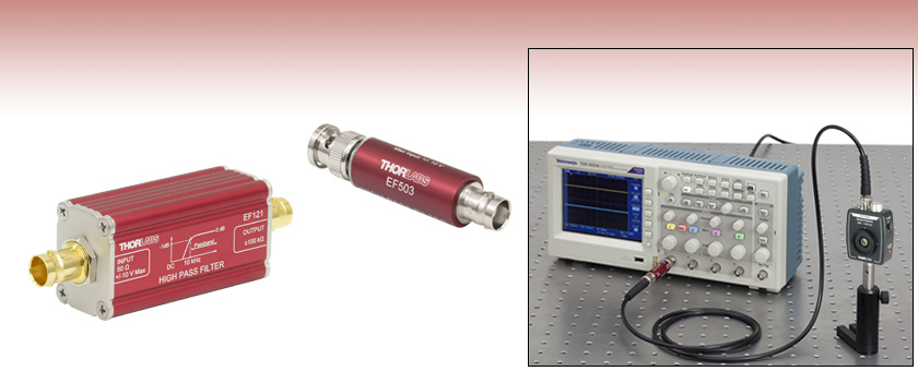
- Passive High-Pass Electrical Filters
- Rejection: 40 dB Minimum, 60 dB Typical
- Terminates Directly into High-Impedance Test Equipment
- 1 dB Cutoff Frequencies Available from 1.2 kHz to 10 MHz
Application Idea
EF507 Used in Conjunction with a High-Impedance Oscilloscope and Amplified Photodetector
EF121
>10.5 kHz High-Pass Filter
EF503
>220 kHz High-Pass Filter

Please Wait
Click to Enlarge
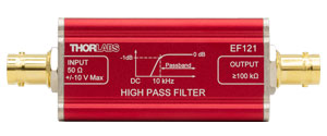
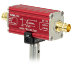
Figure 1.1 Each EF100 Series in-line filter features two female BNC connectors. They are engraved with the part number, the type of filter, the passband range, and the response curve.
| Electrical Filters Selection Guide |
|---|
| Low-Pass Electrical Filters |
| High-Pass Electrical Filters |
| DC Block and Mains Hum Electrical Filters |
| DC Block Filter for RF |
Click to Enlarge
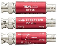
Figure 1.2 Each EF500 Series coaxial filter has a male and female BNC connector. They are engraved with the part number, the type of filter, the passband range, and the response curve.
Features
- 5th or 6th Order Elliptic High-Pass Filter Design
- Selection of 1 dB Passband Windows from 1.2 kHz to 10 MHz
- Can be Driven by Any 50 Ω Load
- Designed to be Terminated into High-Impedance Equipment
- No External Power Supply Required
Thorlabs' Passive Electrical Filters are feedthrough BNC filters that allow the user to filter unwanted signals and noise with a guaranteed minimum rejection of 40 dB. These high-pass filters are designed to be driven by a low-impedance source and terminated directly into high-impedance equipment. Examples of typical 50 Ω (low-impedance) sources are Thorlabs' amplified photodetectors, while examples of high-impedance equipment include 1 MΩ oscilloscope terminals, DAQ boards, and 100 kΩ op-amp inputs. This page contains our series of high-pass electrical filters. Thorlabs also offers low-pass electrical filters and DC block electrical filters.
These are passive filters; therefore, no power supply is needed to run these devices. Additionally, they will not display any of the intermodulation distortions that are often observed when using active filters. Passive filters also have lower noise floors and lower thermal emission than their active counterparts, giving these filters higher signal-to-noise capabilities. Each filter is engraved with the part number, passband range, input/output impedance values, and a frequency response curve.
High-Order Elliptic Filters
To ensure excellent suppression of frequencies in the stopband region, our 5th and 6th order high-pass filters are designed as high-order elliptic filters, providing superb attenuation of low frequency components. The Tables G1.1 and G2.1 include more information, such as the 3 dB, 30 dB, and 40 dB stopband frequencies.
Elliptic filters, also known as Cauer filters, produce some of the steepest signal attenuations before the passband when compared to most other passive filters (see Tables G1.1 and G2.1 for the filter's frequency response). This property ensures that these filters are well suited for applications that require severe attenuation of stopband frequencies close to the passband.
In-Line and Coaxial Package Designs
Thorlabs offers both in-line and coaxial BNC feedthrough styled filters (see Figures 1.1 and 1.2). The EF100 series filters are in-line and feature a box design with two female BNC connectors. The in-line design is intended to be used in between two BNC cables. The EF500 series filters are coaxial and feature a cylindrical design with a male and female BNC connector. This allows the filter to be directly attached to a device, such as an oscilloscope (see image above). Due to the larger size of the in-line filters, it is not recommended that these filters be attached directly to a measurement device. The larger size of in-line filters over coaxial filters is due to the inverse relationship between the filter frequency and the size of the internal electrical components inside the housing.
| Posted Comments: | |
MIKE QUAYLE
(posted 2025-05-07 20:49:40.837) Hello,
I am looking for a 50 Ohm BNC connector high-pass filter with a cutoff frequency of 20 Hz. Can you make custom? ksosnowski
(posted 2025-05-08 10:53:15.0) Hello Mike, thanks for reaching out to us. Unfortunately we do not offer custom cutoff frequencies for our electrical filters. However our circuit boards like EEAPCB1 and electrical housings like EEA14 allow for users to implement designs with different passbands in a similar inline filter format. I have reached out directly to discuss your application in further detail. Minsuk Lee
(posted 2021-06-03 13:52:11.597) To whom it may concern,
What are the response times of EF513 and EF515?
I am currently filtering the balanced detector signal using EF513 and EF515. I need to know the time delays to figure out k-clock delay of SS-OCT system.
Best regards,
Minsuk Lee cdolbashian
(posted 2021-08-19 04:50:57.0) Thank you for reaching out to us at Thorlabs. After clarifying your question, you are looking for the delay between the input and output signal. We unfortunately do not have this information. yazhou wang
(posted 2020-12-15 15:36:17.05) Hi,
Since the filter output is designed to terminate directly into high-impedance test equipment, so maybe it is suitable to connect to your voltage amplifier AMP200? Thanks. asundararaj
(posted 2020-12-23 07:17:35.0) Thank you for contacting Thorlabs. Yes, our electrical filters can be used with the AMP200, as long as the input voltages are not exceeded. Beyond this, the amplifier is saturated. The AMP200 when connected via Hi-Z, we spec the output voltage to be ±2 V. Steen Madsen
(posted 2019-12-17 06:51:03.377) Hi
First, thank you for some fantastic filter products. We have just bought the whole range of LP and HP filters.
Will you introduce more in the near future?
Specifically we would be interested in:
HP15MHz
HP20MHz
LP20MHz
Or at least in the range above 10MHz, possibly in-between EF510, EF513 asundararaj
(posted 2019-12-17 04:41:16.0) Thank you for your valuable feedback. While we do not have plans to introduce more of these filters in the near future, I will suggest these new product requests in our internal engineering forum. Ichentoolstw
(posted 2019-03-12 09:30:27.953) To whom it may concern
I would like to know,if I order EF-125 for 1pc,how long it get to Taiwan?
Thanks your attation!
BEST REGARDS
Gerry hsu
Ichen Tools co.,LTD
E-mail add:ichentoolstw @gmail.com YLohia
(posted 2019-04-05 03:36:51.0) Hello, stock item quotes and requests should be sent to sales@thorlabs.com. We have reached out to you directly. mikael.malmstrom
(posted 2018-09-25 15:51:55.403) My DAQ only has a 50Ohm impedance input will it still work or will I se allot of ringing?
(BTW why do you need the Captcha for logged in users?) YLohia
(posted 2018-09-25 04:39:40.0) Hello, thank you for contacting Thorlabs. This product line guarantees the spec relative dB pass-band for input into high impedance voltage transfer systems. We don't have data on the exact transfer function when used with a 50 Ω system, since it can depend also on the type of measurement device. They are not really designed for the 50 Ω power transfer systems of some network analyzers, but it is possible to use a 50 Ω scope. Using a 50 Ω scope, we expect the pass band to narrow. We have noted that many customers are happy using the EF500 series product family at impedances below 100 kOhm. The impedance mismatch may, however, cause ringing in some situations. benjamin.judkewitz
(posted 2018-09-04 10:07:01.987) Can multiple filters be used serially (e.g. high and low pass to make a band-pass)? llamb
(posted 2018-09-04 08:41:23.0) Thank you for contacting Thorlabs. Our electrical filters are designed to be connected to a low-impedance input and to a high-impedance output. Using them serially would mismatch the impedances and likely lead to unwanted ringing effects. |

Click for Details
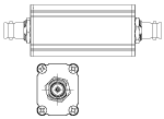
Figure G1.2 Mechanical Drawing of In-Line Design
The in-line package of these filters offers two female BNC connectors.
| Table G1.1 Specifications | ||||||
|---|---|---|---|---|---|---|
| Item #a | EF111 | EF113 | EF115 | EF121 | EF123 | EF125 |
| 1 dB Passband Windowb | >1.2 kHz | >2.2 kHz | >5.0 kHz | >10.5 kHz | >22.2 kHz | >52 kHz |
| 3 dB Rejection | <780 Hz | <1.74 kHz | <4.1 kHz | <9.0 kHz | <18.0 kHz | <41.0 kHz |
| 30 dB Rejection | <550 Hz | <0.78 kHz | <2.4 kHz | <6.6 kHz | <11.8 kHz | <26.0 kHz |
| 40 dB Rejection | <250 Hz | <0.58 kHz | <1.7 kHz | <4.4 kHz | <10.8 kHz | <24.3 kHz |
| Frequency Response Curve (Click for Graph) |
Raw Data |
Raw Data |
Raw Data |
Raw Data |
Raw Data |
Raw Data |
| 1 dB Window Exceptions (Click for Graph) |
||||||
| Source Impedance (Typical) | 50 Ω | |||||
| Load Impedance (Typical)c | ≥100 kΩ | |||||
| Input Voltage (Maximum) | ±10 V | |||||
| Storage Temperature | -20 to 70 °C | |||||

The coaxial package of these filters offers one male and one female BNC connector.
| Table G2.1 Specifications | |||||||
|---|---|---|---|---|---|---|---|
| Item #a | EF505 | EF503 | EF507 | EF517 | EF509 | EF513 | EF515 |
| 1 dB Passband Windowb | >130 kHz | >220 kHz | >500 kHz | >1 MHz | >1.8 MHz | >6.7 MHz | >10 MHz |
| 3 dB Rejection | <77 kHz | <114 kHz | <305 kHz | <592 kHz | <1.1 MHz | <4 MHz | <5.6 MHz |
| 30 dB Rejection | <56.9 kHz | <83 kHz | <227.5 kHz | <438 kHz | <800 kHz | <3 MHz | <4.37 MHz |
| 40 dB Rejection | <38 kHz | <77 kHz | <217 kHz | <411 kHz | <750 kHz | <2.85 MHz | <4.15 MHz |
| Frequency Response Curve (Click for Graph) |
Raw Data |
Raw Data |
Raw Data |
Raw Data |
Raw Data |
Raw Data |
Raw Data |
| Source Impedance (Typical) | 50 Ω | ||||||
| Load Impedance (Typical)c | ≥100 kΩ | ||||||
| Input Voltage (Maximum) | ±10 V | ||||||
| Storage Temperature | -20 to 70 °C | ||||||

Click for Details
Figure G2.2 Mechanical Drawing of Coaxial Design

Aluminum Clamps, Post Mountable
These anodized aluminum clamps provide secure mounting for the in-line filters sold above. Each clamp can snap onto the side of the device and the flexure lock can be tightened using the 2 mm (5/64") hex locking screw on the side. The ECM100 fits onto the 1.00" side, while the ECM125 fits onto the 1.25" side.
Each clamp has a #8 (M4) counterbore on the bottom, allowing it to be mounted on a Ø1/2" post or any surface with an 8-32 (M4) tap. The clamp must be mounted via the counterbore before the device is attached, as the counterbore will not be accessible once the housing is secured in the clamp.
Plastic Clamp, Double Sided
The EPS125 clamp is designed to connect two in-line filters for compact setups; the clamp attaches to the 1.25" side of each device.
 Products Home


 Zoom
Zoom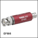

 High-Pass Electrical Filters