

Free-Space Si Avalanche Photodetectors

- High-Speed Response Up to 1 GHz
- Conversion Gains up to 2.65 × 10⁹ V/W
- Wavelength Range of 200 - 1000 nm or 400 - 1000 nm
- Temperature-Compensated and Variable-Gain Versions Available
APD210
High-Speed APD
APD130A2
Temperature-Compensated APD
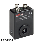
APD430A
Variable-Gain,
Temperature-Compensated APD
OVERVIEW
| Free-Space Si APD Selection Guide | |||
|---|---|---|---|
| Item # | Wavelength Range |
Bandwidth (3 dB) |
Type (Quick Links) |
| APD130A2(/M) | 200 - 1000 nm | DC - 50 MHz | Temperature Compensated |
| APD130A(/M) | 400 - 1000 nm | ||
| APD440A2 | 200 - 1000 nm | DC - 0.1 MHz | Variable Gain, Temperature Compensated |
| APD410A2(/M) | DC - 10 MHz | ||
| APD430A2(/M) | DC - 400 MHz | ||
| APD440A | 400 - 1000 nm | DC - 0.1 MHz | |
| APD410A(/M) | DC - 10 MHz | ||
| APD430A(/M) | DC - 400 MHz | ||
| APD410 | 200 - 1000 nm | 5 - 900 MHz | Variable Gain, Temperature Compensated, High Speed |
| APD210 | 400 - 1000 nm | 5 - 1000 MHz | |

Click to Enlarge
The above plot shows the M factor stability of our temperature-compensated avalanche photodetectors. The blue shaded region indicates the temperature range over which the M factor stability is guaranteed to within ±3%.
Features
- Noise Equivalent Powers (NEP) as Low as 2.5 fW/√Hz
- Max Bandwidth Up to 1 GHz at 3 dB
- Temperature-Compensated Versions Provide M Factor Stability of ≤±3% Over 18 to 28 °C
- Variable Gain Detectors Available: M Factor from 5 to 50 or 10 to 100
- Free-Space Optical Input with Internal SM05 and External SM1 Threading for Lens Tubes
- Power Supply Included
Thorlabs' Free-Space Silicon Avalanche Photodetectors (APD) are designed to offer increased sensitivity and lower noise compared to standard PIN detectors, making them ideal for applications with low optical power levels. In addition to our standard APDs, versions featuring variable gain (i.e., M factor) and/or temperature compensation are offered.
In general, avalanche photodiodes use an internal gain mechanism to increase sensitivity. A high reverse bias voltage is applied to the diodes to create a strong electric field. When an incident photon generates an electron-hole pair, the electric field accelerates the electrons, leading to the production of secondary electrons by impact ionization. The resulting electron avalanche can produce a gain factor of several hundred times, described by a multiplication factor, M, that is a function of both the reverse bias voltage and temperature. In general, the M factor increases with lower temperatures and decreases with higher temperatures. Similarly, the M factor will increase when the reverse bias voltage is raised and decrease when the reverse bias voltage is lowered.
Our APD130A2(/M) and APD130A(/M) temperature-compensated APDs feature integrated thermistors that adjust the bias voltage to compensate for the effect of temperature changes on the M factor. A comparison with our non-temperature-compensated APDs is provided in the graph to the right.
In addition to being temperature compensated, our variable-gain APD400 series detectors allow the reverse bias voltage across the diodes to be adjusted via a rotary knob on the side of the housing, which varies the M factor from 5 to 50 or 10 to 100.
Thorlabs offers Menlo Systems' APD410 and APD210 Variable-Gain Avalanche Photodetectors, which offer high-speed responses up to 900 MHz or 1 GHz at 3 dB, respectively. Additionally, we offer spectral-flattening filters that are designed to improve the response uniformity of our silicon photodiodes and detectors; click here to learn more.
A complete list of all of our APDs can be found on the Selection Guide tab. Please note that our Single Photon Detectors are the only avalanche photodetectors suitable for single photon counting.
| Avalanche Photodiode Selection Guidea |
|---|
| Free-Space Si APDs |
| Fiber-Coupled Si APDs |
| Free-Space InGaAs APDs |
| Fiber-Coupled InGaAs APDs |
SPECS
Click on the yellow boxes below to view specifications for each type of photodetector.
Temperature-Compensated Si Avalanche Photodetectors
All technical data are valid at 23 ± 5 °C and 45% ± 15% relative humidity (non-condensing).
| Item # | APD130A2(/M) | APD130A(/M) |
|---|---|---|
| Detector Type | UV Enhanced Silicon APD |
Silicon APD |
| Wavelength Range | 200 - 1000 nm | 400 - 1000 nm |
| Output Bandwidth (3 dB) | DC - 50 MHz | |
| Active Area Diameter | 1 mm | |
| Typical Max Responsivity | 25 A/W @ 600 nm (M = 50) |
25 A/W @ 800 nm (M = 50) |
| M Factora,b | 50 | |
| M Factor Temperature Stabilityc | ±2% (Typical); ±3% (Max) |
±2% (Typical); ±3% (Max) |
| Transimpedance Gain | 50 kV/A with 50 Ω Terminationd 100 kV/A for High-Impedance Termination |
|
| Max Conversion Gaine,f | 2.5 x 10⁶ V/W | |
| CW Saturation Power | 1.5 µW | |
| Max Input Powerg | 1 mW | |
| Minimum NEP (DC - 50 MHz)e,h |
0.21 pW/√Hz | 0.20 pW/√Hz |
| Integrated Noise (DC - 50 MHz) |
1.4 nW (RMS) | 1.5 nW (RMS) |
| Electrical Outputs | 50 Ω BNC | |
| Max Output Voltage | 1.8 V with 50 Ω Termination 3.6 V with High-Impedance Termination |
|
| DC Offset Electrical Output | <±15 mV | |
| Power Supplyi | ±12 V @ 250 mA (100/120/230 VAC, 50 - 60 Hz, Switchable) |
|
| General | ||
| Operating Temperature Range | 0 to 40 °C (Non-Condensing) | |
| Storage Temperature Range | -40 to 70 °C | |
| Device Dimensions (H x W x D) |
75.5 mm x 50.8 mm x 27.4 mm (2.97" x 2.00" x 1.08") |
|
| Weight | <0.1 kg | |
Variable-Gain, Temperature-Compensated Si Avalanche Photodetectors
All technical data are valid at 23 ± 5 °C and 45% ± 15% relative humidity (non-condensing).
| Item # | APD440A2 | APD410A2(/M) | APD430A2(/M) |
|---|---|---|---|
| Detector Type | UV Enhanced Silicon APD | ||
| Wavelength Range | 200 - 1000 nm | ||
| Output Bandwidth (3 dB)a | DC - 100 kHz | DC - 10 MHz | DC - 400 MHz |
| Active Area Diameter | 1.0 mm | 0.5 mm | 0.2 mm |
| Typical Max Responsivity | 25 A/W @ 600 nm (M = 50) | 25 A/W @ 600 nm (M = 50) | 50 A/W @ 600 nm (M = 100) |
| Responsivity Graph (Click to View) |
|||
| M Factor Adjustment Rangeb,c | 5 - 50 (Continuous) | 10 - 100 (Continuous) | |
| M Factor Temperature Stabilityd | ±2% (Typical); ±3% (Max) | ||
| Transimpedance Gain | 25 MV/A (50 Ω Termination) 50 MV/A (High-Z Termination) |
250 kV/A (50 Ω Termination)e 500 kV/A (High-Z Termination) |
5 kV/A (50 Ω Termination)e 10 kV/A (High-Z Termination) |
| Max Conversion Gainf,g | 1.25 × 10⁹ V/W | 12.5 × 10⁶ V/W | 5.0 × 10⁵ V/W |
| CW Saturation Power | 3.28 nW @ 600 nm, M = 50 32.8 nW @ 600 nm, M = 5 |
0.32 µW @ 600 nm, M = 50 3.20 µW @ 600 nm, M = 5 |
8.0 µW @ 600 nm, M = 100 80 µW @ 600 nm, M = 10 |
| Max Input Powerh | 1 mW | ||
| Minimum NEPi | 2.5 fW/√Hz (DC - 100 kHz) | 0.09 pW/√Hz (DC - 10 MHz) | 0.15 pW/√Hz (DC - 100 MHz) |
| Integrated Noise (RMS)a | 0.8 pW (DC - 100 kHz) | 0.28 nW (DC - 10 MHz) | 6 nW (DC - 400 MHz) |
| Electrical Outputs | 50 Ω BNC | ||
| Max Output Voltage | 2.0 V (50 Ω Termination); 4.1 V (High-Z Termination) | ||
| DC Offset Electrical Output | <±3 mV | ||
| Included Power Supplyj | ±12 V @ 250 mA (100/120/230 VAC, 50 - 60 Hz, Switchable) | ||
| General | |||
| Operating Temperature Range | 0 to 40 °C (Non-Condensing) | ||
| Storage Temperature Range | -40 to 70 °C | ||
| Device Dimensions (H x W x D) |
2.93" x 2.21" x 1.08" (74.5 mm x 56.1 mm x 27.4 mm) |
2.97" x 2.20" x 1.09" (75.5 mm x 55.8 mm x 27.6 mm) |
|
| Weight | 0.12 kg | 0.1 kg | |
| Item # | APD440A | APD410A | APD430A |
|---|---|---|---|
| Detector Type | Silicon APD | ||
| Wavelength Range | 400 - 1000 nm | ||
| Output Bandwidth (3 dB)a | DC - 100 kHz | DC - 10 MHz | DC - 400 MHz |
| Active Area Diameter | 1.0 mm | 1.0 mm | 0.5 mm |
| Typical Max Responsivity | 53 A/W @ 800 nm (M = 100) | ||
| Responsivity Graph (Click to View) |
|||
| M Factor Adjustment Rangeb | 10 - 100 (Continuous) | ||
| M Factor Temperature Stabilityc | ±2% (Typical); ±3% (Max) | ||
| Transimpedance Gain | 25 MV/A (50 Ω Termination) 50 MV/A (High-Z Termination) |
250 kV/A (50 Ω Termination)d 500 kV/A (High-Z Termination) |
5 kV/A (50 Ω Termination)d 10 kV/A (High-Z Termination) |
| Max Conversion Gaine,f | 2.65 × 10⁹ V/W | 26.5 × 10⁶ V/W | 5.3 × 10⁵ V/W |
| CW Saturation Power | 1.54 nW @ 800 nm, M = 100 15.4 nW @ 800 nm, M = 10 |
0.15 µW @ 800 nm, M = 100 1.50 µW @ 800 nm, M = 10 |
8.0 µW @ 800 nm, M = 100 80 µW @ 800 nm, M = 10 |
| Max Input Powerg | 1 mW | ||
| Minimum NEPf,g | 3.5 fW/√Hz (DC - 100 kHz) | 0.04 pW/√Hz (DC - 10 MHz) | 0.14 pW/√Hz (DC - 100 MHz) |
| Integrated Noise (RMS)a | 1.1 pW (DC - 100 kHz) | 0.13 nW (DC - 10 MHz) | 5.5 nW (DC - 400 MHz) |
| Electrical Outputs | 50 Ω BNC | ||
| Max Output Voltage | 2.0 V (50 Ω Termination); 4.1 V (High-Z Termination) | ||
| DC Offset Electrical Output | <±3 mV | ||
| Included Power Supplyi | ±12 V @ 250 mA (100/120/230 VAC, 50 - 60 Hz, Switchable) | ||
| General | |||
| Operating Temperature Range | 0 to 40 °C (Non-Condensing) | ||
| Storage Temperature Range | -40 to 70 °C | ||
| Device Dimensions (H x W x D) |
2.93" x 2.21" x 1.08" (74.5 mm x 56.1 mm x 27.4 mm) |
2.97" x 2.20" x 1.09" (75.5 mm x 55.8 mm x 27.6 mm) |
|
| Weight | 0.12 kg | 0.1 kg | |
Variable-Gain, Temperature-Compensated, High-Speed Si Avalanche Photodetectors
| Item # | APD410 | APD210 |
|---|---|---|
| Detector Type | Si APD | |
| Optical Input | Free Spacea | |
| Wavelength Range | 200 - 1000 nm | 400 - 1000 nm |
| Damage Threshold | 10 mW | 10 mW |
| Active Area Diameter | 0.2 mm | 0.5 mm |
| Frequency Range | 1 MHz - 1600 MHz | |
| 3 dB Bandwidth | 5 MHz - 900 MHz | 5 MHz - 1000 MHz |
| Rise Time | 500 ps | 500 ps |
| Conversion Gain (Max)b | 4.5 x 10⁴ V/W @ 650 nm | 2.5 x 10⁵ V/W @ 800 nm |
| NEP (Calculated)c | 87.6 pW/√Hz | 0.24 pW/√Hz |
| Dark State Noise Leveld | -80 dBm | |
| M Factor | 50 | 100 |
| Typical Max Responsivity | 22 A/W @ 650 nm | 50 A/W @ 800 nm |
| Output Impedance | 50 Ω | |
| Output Connector | BNC | |
| Output Coupling | AC | |
| Current Consumption (Max) | 200 mA | |
| Supply Voltagee | +12 to +15 V | |
| Operating Temperature | 10 to 40 °C | |
| Storage Temperature | -20 to +85 °C | |
| Storage Humidity | 10% - 90% RH | |
| Device Dimensions | 60 mm x 50 mm x 47.5 mm (2.36" x 1.97" x 1.87") |
|
| Performance Graphs (Click to View) | ||
|---|---|---|
| Item # | APD410 | APD210 |
| Responsivity |  |
 |
| Frequency Response |  |
 |
| Time Characteristics |  |
 |
| Rise Time |  |
 |
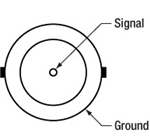
PIN DIAGRAMS
BNC Female Output (Photodetector)
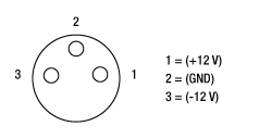
APD Male (Power Cables)
APD Female (Photodetector)
FIBER COUPLING&NBSP;
| Components for Fiber Couplinga | |
|---|---|
| Item # | Description |
| - | Free-Space Avalanche Photodetector |
| LM1XY(/M) | Translating Lens Mount for Ø1" Optics |
| SM1L10 | SM1 (1.035"-40) Lens Tube, 1" Long |
| - | Fiber Collimator (Dependent on Fiber) |
| AD11F or AD12F | SM1-Threaded Adapters for Ø11 or Ø12 mm Fiber Collimators (Dependent on Collimator) |
| - | Mounted Molded Aspheric Lens (Dependent on Collimator) |
| S1TM06, S1TM08, S1TM09, S1TM10, or S1TM12 |
SM1-Threaded Adapter for Molded Aspheric Lens Cell (Dependent on Lens) |

Click to Enlarge
Output from a fiber is coupled into the photodetector using an aspheric lens to focus the signal onto the detector active area.
Fiber Coupling to Free-Space APDs
A fiber coupling mechanism can be constructed for our free-space APDs using standard optomechanics. In fiber coupling applications, we recommend taking into account the divergence of light from the fiber tip to ensure that all of the signal is focused onto the detector active area. When using a standard fiber connector adapter with a detector with an active area smaller than Ø1 mm, high coupling losses and degradation of the frequency response may occur.
To achieve high coupling efficiency, a fiber collimation package, focusing lens, and X-Y translator should be used, as shown in the photo to the right. The avalanche photodetector is shown with a fiber collimator, lens tube collimator adapter, lens tube, and X-Y translation mount. An adapter inside the lens tube holds an aspheric lens (not visible) to focus the collimated light onto the active area of the detector. The X-Y translation mount corrects for any centering issues.
Please note that Thorlabs also offers the APD431A fiber-coupled Si photodetector, which features an M12 x 0.15-threaded flange that is directly compatible with our M12 x 0.5-threaded fiber connector adapters. This compact and robust mechanism allows for easy fiber coupling with high reproducibility. The M12 x 0.5-threaded flange can be added to any of Thorlabs' Avalanche Photodetectors to provide robust fiber-coupling capabilities. Please contact Tech Support for more information.
PULSE CALCULATIONS
Pulsed Laser Emission: Power and Energy Calculations

Determining whether emission from a pulsed laser is compatible with a device or application can require referencing parameters that are not supplied by the laser's manufacturer. When this is the case, the necessary parameters can typically be calculated from the available information. Calculating peak pulse power, average power, pulse energy, and related parameters can be necessary to achieve desired outcomes including:
- Protecting biological samples from harm.
- Measuring the pulsed laser emission without damaging photodetectors and other sensors.
- Exciting fluorescence and non-linear effects in materials.
Pulsed laser radiation parameters are illustrated in Figure 1 and described in the table. For quick reference, a list of equations is provided below. The document available for download provides this information, as well as an introduction to pulsed laser emission, an overview of relationships among the different parameters, and guidance for applying the calculations.
|
Equations: |
||||
 |
and |  |
||
 |
||||
 |
||||
 |
||||
Peak power and average power calculated from each other: |
||||
 |
and |  |
||
| Peak power calculated from average power and duty cycle*: | ||||
 |
*Duty cycle ( ) is the fraction of time during which there is laser pulse emission. ) is the fraction of time during which there is laser pulse emission. |
|||

Click to Enlarge
Figure 1: Parameters used to describe pulsed laser emission are indicated in the plot (above) and described in the table (below). Pulse energy (E) is the shaded area under the pulse curve. Pulse energy is, equivalently, the area of the diagonally hashed region.
| Parameter | Symbol | Units | Description | ||
|---|---|---|---|---|---|
| Pulse Energy | E | Joules [J] | A measure of one pulse's total emission, which is the only light emitted by the laser over the entire period. The pulse energy equals the shaded area, which is equivalent to the area covered by diagonal hash marks. | ||
| Period | Δt | Seconds [s] | The amount of time between the start of one pulse and the start of the next. | ||
| Average Power | Pavg | Watts [W] | The height on the optical power axis, if the energy emitted by the pulse were uniformly spread over the entire period. | ||
| Instantaneous Power | P | Watts [W] | The optical power at a single, specific point in time. | ||
| Peak Power | Ppeak | Watts [W] | The maximum instantaneous optical power output by the laser. | ||
| Pulse Width |  |
Seconds [s] | A measure of the time between the beginning and end of the pulse, typically based on the full width half maximum (FWHM) of the pulse shape. Also called pulse duration. | ||
| Repetition Rate | frep | Hertz [Hz] | The frequency with which pulses are emitted. Equal to the reciprocal of the period. | ||
Example Calculation:
Is it safe to use a detector with a specified maximum peak optical input power of 75 mW to measure the following pulsed laser emission?
- Average Power: 1 mW
- Repetition Rate: 85 MHz
- Pulse Width: 10 fs
The energy per pulse:

seems low, but the peak pulse power is:

It is not safe to use the detector to measure this pulsed laser emission, since the peak power of the pulses is >5 orders of magnitude higher than the detector's maximum peak optical input power.
SELECTION GUIDE
Avalanche Photodetector Selection Guide
| Item # | Detector Type |
Wavelength Range |
3 dB Bandwidth | Active Area Diameter |
M Factor | Typical Max Responsivity |
Max Conversion Gaina |
Variable Gain |
Temperature Compensated |
Fiber-Coupledb |
|---|---|---|---|---|---|---|---|---|---|---|
| APD440A2 | UV Enhanced Silicon APD |
200 - 1000 nm | DC - 0.1 MHz | 1 mm | 5 - 50 | 25 A/W @ 600 nm (M = 50) | 1.25 x 10⁹ V/W | - | ||
| APD410A2 | DC - 10 MHz | 0.5 mm | 5 - 50 | 25 A/W @ 600 nm (M = 50) | 12.5 x 10⁶ V/W | - | ||||
| APD130A2 | DC - 50 MHz | 1 mm | 50 | 25 A/W @ 600 nm (M = 50) | 2.5 x 10⁶ V/W | - | - | |||
| APD430A2 | DC - 400 MHz | 0.2 mm | 10 - 100 | 50 A/W @ 600 nm (M = 100) | 5.0 x 10⁵ V/W | - | ||||
| APD410 | 5 - 900 MHzc | 0.2 mm | 50 | 22 A/W @ 650 nm (M = 50) | 4.5 x 10⁴ V/Wd | - | ||||
| APD440A | Silicon APD | 400 - 1000 nm | DC - 0.1 MHz | 1 mm | 10 - 100 | 53 A/W @ 800 nm (M = 100) | 2.65 x 10⁹ V/W | - | ||
| APD410A | DC - 10 MHz | 1.0 mm | 10 - 100 | 53 A/W @ 800 nm (M=100) | 26.5 x 10⁶ V/W | - | ||||
| APD130A | DC - 50 MHz | 1 mm | 50 | 25 A/W @ 800 nm (M = 50) | 2.5 x 10⁶ V/W | - | - | |||
| APD430A | DC - 400 MHz | 0.5 mm | 10 - 100 | 53 A/W @ 800 nm (M = 100) | 5.3 x 10⁵ V/W | - | ||||
| APD431A | DC - 400 MHze | 0.5 mm | 10 - 100 | 53 A/W @ 800 nm (M = 100) | 5.3 x 10⁵ V/W | |||||
| APD210 | 5 - 1000 MHzc | 0.5 mm | 100 | 50 A/W @ 800 nm (M = 100) | 2.5 x 10⁵ V/Wf | - | ||||
| APD130C | InGaAs APD | 900 - 1700 nm | DC - 50 MHz | 0.2 mm | 10 | 9 A/W @ 1500 nm (M = 10) | 0.9 x 10⁶ V/W | - | - | |
| APD410C | DC - 10 MHz | 0.2 mm | 4 - 20 | 18 A/W @ 1550 nm (M = 20) | 9.0 x 10⁶ V/W | - | ||||
| APD430C | DC - 400 MHz | 0.2 mm | 4 - 20 | 18 A/W @ 1550 nm (M = 20) | 1.8 x 10⁵ V/W | - | ||||
| APD431C | DC - 400 MHze | 0.2 mm | 4 - 20 | 18 A/W @ 1550 nm (M = 20) | 1.8 x 10⁵ V/W | |||||
| APD450C | 1260 - 1620 nm | 0.3 - 1600 MHz | 1.5 mmg | 2 - 10 | 9 A/W @ 1550 nm (M = 10) | 45 × 103 V/W | - | |||
| APD310 | 850 - 1650 nm | 5 - 1000 MHzc | 0.04 mm | 30 | 0.9 A/W @ 1550 nm (M = 30) | 2.5 x 10⁴ V/Wh | - |
Temperature-Compensated Si Avalanche Photodetectors

| Key Specificationsa | ||
|---|---|---|
| Item # | APD130A2(/M) | APD130A(/M) |
| Detector Type | UV-Enhanced Silicon APD |
Silicon APD |
| Wavelength Range | 200 - 1000 nm | 400 - 1000 nm |
| Output Bandwidth (3 dB) | DC - 50 MHz | |
| Active Area Diameter | 1 mm | |
| Typical Max Responsivity (M = 50) | 25 A/W @ 600 nm | 25 A/W @ 800 nm |
| Responsivity Graph (Click to View) |
 |
|
| Transimpedance Gain | 50 kV/A (50 Ω Termination) 100 kV/A (High-Z Termination) |
|
| Max Conversion Gainb | 2.5 × 10⁶ V/W | |
| M Factor | 50 | |
| M Factor Temperature Stabilitya | ±2% (Typical); ±3% (Max) | |
| Saturation Power (CW) | 1.5 µW | |
| Minimum NEP (DC - 50 MHz)b | 0.21 pW/√Hz | 0.20 pW/√Hz |
| Dimensions (H x W x D) | 2.97" x 2.00" x 1.08" | |
- Temperature Compensated to Provide M Factor Stability of ≤±3% Over 18 to 28 °C
- Internal SM05 and External SM1 Threads Accept Most Fiber Adapters, Lens Tubes, and Other Components
- Power Supply Included
Thorlabs' APD130A2(/M) and APD130A(/M) Free-Space Avalanche Photodetectors feature an integrated thermistor that maintains an M factor stability of ±3% or better over 23 ± 5 °C by adjusting the bias voltage across the avalanche photodiode, supplying improved output stability in environments with temperature variations.
The orientation of the mechanical and electrical connections, combined with the compact design, ensures that these detectors can fit into tight spaces. Three 8-32 (M4) mounting holes, one on each edge of the housing, further ensure easy integration into complicated mechanical setups. The housing also provides compatibility with both our SM05- and SM1-Series Lens Tubes. An internally SM1-threaded cap is included.
Our SM1-threaded fiber adapters are compatible with these detectors. The internally SM1-threaded adapters can be mated directly to the housing, and are available below. To use our externally SM1-threaded fiber adapters, an internally SM1-threaded lens tube will be required to mate the fiber adapter to the detector's housing. The externally SM05-threaded fiber adapters are not compatible with these detectors.
Part Number | Description | Price | Availability |
|---|---|---|---|
APD130A2/M | Si Avalanche Photodetector, Temperature Compensated, UV Enhanced, 200 - 1000 nm, M4 Taps | $1,397.00 | 3 weeks |
APD130A/M | Si Avalanche Photodetector, Temperature Compensated, 400 - 1000 nm, M4 Taps | $1,397.00 | Today |
APD130A2 | Si Avalanche Photodetector, Temperature Compensated, UV Enhanced, 200 - 1000 nm, 8-32 Taps | $1,397.00 | 3 weeks |
APD130A | Si Avalanche Photodetector, Temperature Compensated, 400 - 1000 nm, 8-32 Taps | $1,397.00 | Today |
Variable-Gain, Temperature-Compensated Si Avalanche Photodetectors

Click to Enlarge
The M Factor is controlled by a knob on the side of the APD.
- Continuously Variable Gain
- Temperature Compensated to Provide M Factor Stability of ≤±3% Over 18 to 28 °C
- Internal SM05 and External SM1 Threads Accept Most Fiber Adapters, Lens Tubes, and Other Components
- Power Supply Included
These Free-Space Avalanche Photodetectors feature a variable gain that can be controlled by a knob on the right side of the housing. Like the APD130A detectors above, these devices feature an integrated thermistor that maintains an M factor stability of ±3% or better over 23 ± 5 °C by adjusting the bias voltage across the avalanche photodiode. Compared to the standard and temperature-controlled APDs above, the APD430A2 and APD430A detectors also offer a larger usable bandwidth of DC to 400 MHz. The APD410A2 and APD410A detectors offer a slightly smaller usable bandwidth (DC to 10 MHz), but with higher sensitivity. The APD440A2 and APD440A detectors offer high transimpedance gain with a lower max bandwidth of 100 kHz.
The orientation of the mechanical and electrical connections, combined with the compact design, ensures that these detectors can fit into tight spaces. Three 8-32 (M4) mounting holes, one on each edge of the housing, further ensure easy integration into complicated mechanical setups. The housing also provides compatibility with both our SM05- and SM1-Series Lens Tubes. An internally SM1-threaded cap is included.
Fiber Coupling Note:
A fiber coupling mechanism can be constructed for our free-space APDs using standard optomechanics. For fiber-coupled applications, we do not recommend using fiber connector adapters such as Thorlabs' S120-FC with the APD410A2(/M), APD430A2(/M), and APD430A detectors due to the small size of the sensors. High coupling losses and degradation of the frequency response may occur. To achieve high coupling efficiency, a fiber collimation package, focusing lens, and X-Y translator should be used. See the Fiber Coupling tab for details.
Please note that Thorlabs also offers the APD431A fiber-coupled Si photodetector, which features an M12 x 0.15-threaded flange that is directly compatible with our M12 x 0.5-threaded fiber connector adapters. This compact and robust mechanism allows for easy fiber coupling with high reproducibility. The M12 x 0.5-threaded flange can be added to any of Thorlabs' Avalanche Photodetectors to provide robust fiber-coupling capabilities. Please contact Tech Support for more information.
| Key Specificationsa | ||||||
|---|---|---|---|---|---|---|
| Item # | APD440A2 | APD410A2(/M) | APD430A2(/M) | APD440A | APD410A(/M) | APD430A(/M) |
| Detector Type | UV-Enhanced Silicon APD | Silicon APD | ||||
| Wavelength Range | 200 - 1000 nm | 400 - 1000 nm | ||||
| Output Bandwidth (3 dB)b | DC - 100 kHz | DC - 10 MHz | DC - 400 MHz | DC - 100 kHz | DC - 10 MHz | DC - 400 MHz |
| Active Area Diameter | 1.0 mm | 0.5 mm | 0.2 mm | 1.0 mm | 1.0 mm | 0.5 mm |
| Typical Max Responsivity | 25 A/W @ M = 50c | 25 A/W @ M = 50c | 50 A/W @ M = 100c | 53 A/W @ M = 100d | ||
| Responsivity Graph (Click to View) |
 |
|||||
| Transimpedance Gain | 25 MV/A (50 Ω) 50 MV/A (High-Z) |
250 kV/A (50 Ω) 500 kV/A (High-Z) |
5 kV/A (50 Ω) 10 kV/A (High-Z) |
25 MV/A (50 Ω) 50 MV/A (High-Z) |
250 kV/A (50 Ω) 500 kV/A (High-Z) |
5 kV/A (50 Ω) 10 kV/A (High-Z) |
| Max Conversion Gaine | 1.25 × 10⁹ V/W | 12.4 × 10⁶ V/W | 5.0 × 10⁵ V/W | 2.65 × 10⁹ V/W | 26.5 × 10⁶ V/W | 5.3 × 10⁵ V/W |
| M Factor Adjustment Range | 5 - 50 (Continuous) | 10 - 100 (Continuous) | ||||
| M Factor Temperature Stabilityf | ±2% (Typical); ±3% (Max) | |||||
| Saturation Power (CW) | 3.28 nW @ M = 50c 32.8 nW @ M = 5 |
0.32 µW @ M = 50c 3.20 µW @ M = 5 |
8.0 µW @ M = 100c 80 µW @ M = 10 |
1.54 nW @ M = 100d 15.4 nW @ M = 10 |
0.15 µW @ M = 100d 1.50 µW @ M = 10 |
8.0 µW @ M = 100d 80 µW @ M = 10 |
| Minimum NEPg | 2.5 fW/√Hz | 0.09 pW/√Hz | 0.15 pW/√Hz | 3.5 fW/√Hz | 0.04 pW/√Hz | 0.14 pW/√Hz |
| Dimensions (H x Wx D) | 2.93" x 2.21" x 1.08" | 2.97" x 2.20" x 1.09" | 2.93" x 2.21" x 1.08" | 2.97" x 2.20" x 1.09" | ||
Part Number | Description | Price | Availability |
|---|---|---|---|
APD410A2/M | Si Variable-Gain Avalanche Detector, Temperature Compensated, UV Enhanced, 200 - 1000 nm, DC - 10 MHz, M4 Taps | $1,457.58 | Today |
APD430A2/M | Si Variable-Gain Avalanche Detector, Temperature Compensated, UV Enhanced, 200 - 1000 nm, DC - 400 MHz, M4 Taps | $1,457.58 | Today |
APD410A/M | Si Variable-Gain Avalanche Detector, Temperature Compensated, 400 - 1000 nm, DC - 10 MHz, M4 Taps | $1,457.58 | Today |
APD430A/M | Si Variable-Gain Avalanche Detector, Temperature Compensated, 400 - 1000 nm, DC - 400 MHz, M4 Taps | $1,457.58 | 3 weeks |
APD440A | Customer Inspired! Si Variable-Gain Avalanche Detector, Temperature Compensated, 400 - 1000 nm, DC - 100 kHz, Universal 8-32 / M4 Taps | $1,300.32 | 3 weeks |
APD440A2 | Customer Inspired! Si Variable-Gain Avalanche Detector, Temperature Compensated, 200 - 1000 nm, DC - 100 kHz, Universal 8-32 / M4 Taps | $1,300.32 | 3 weeks |
APD410A2 | Si Variable-Gain Avalanche Detector, Temperature Compensated, UV Enhanced, 200 - 1000 nm, DC - 10 MHz, 8-32 Taps | $1,457.58 | 3 weeks |
APD430A2 | Si Variable-Gain Avalanche Detector, Temperature Compensated, UV Enhanced, 200 - 1000 nm, DC - 400 MHz, 8-32 Taps | $1,457.58 | Today |
APD410A | Si Variable-Gain Avalanche Detector, Temperature Compensated, 400 - 1000 nm, DC - 10 MHz, 8-32 Taps | $1,457.58 | Lead Time |
APD430A | Si Variable-Gain Avalanche Detector, Temperature Compensated, 400 - 1000 nm, DC - 400 MHz, 8-32 Taps | $1,457.58 | Today |
Variable-Gain, Temperature-Compensated, High-Speed Si Avalanche Photodetectors

| Key Specificationsa | ||
|---|---|---|
| Item # | APD410 | APD210 |
| Detector Type | Silicon APD | |
| Wavelength Range | 200 - 1000 nm | 400 - 1000 nm |
| Frequency Range | 1 - 1600 MHz | |
| 3 dB Bandwidth | 5 - 900 MHz | 5 - 1000 MHz |
| Active Area Diameter | 0.2 mm | 0.5 mm |
| Responsivity Graph (Click to View) |
|
|
| Conversion Gain (Max) | 4.5 x 10⁴ V/W @ 1 GHz, 650 nm | 2.5 × 10⁵ V/W @ 1 GHz, 800 nm |
| NEP (Calculated)b | 87.6 pW/√Hz | 0.24 pW/√Hz |
| M Factor | 50 | 100 |
| Typ. Max Responsivity | 22 A/W @ 650 nm | 50 A/W @ 800 nm |
Applications
- Fast Laser Pulses
- Ultra-Low-Light Signals
- Temperature-Compensated Avalanche Photodiode
- Integrated Radio Frequency Amplifier
- Continuously Adjustable Gain Setting
- Long-Term Field Tested
- Free-Space Optical Input with Internal SM05 (0.535"-40) Threading
- Easy-to-Use Package
- Location-Specific (EU or US) Power Supply Included
Originally developed for the detection of the beat note signal between CW or pulsed lasers, Menlo Systems' Si Avalanche Photodetectors are ideally suited for applications requiring very high sensitivity for low-light input signals in the 200 - 1000 nm or 400 - 1000 nm range. The APD avalanche photodiode series can provide an extremely sensitive alternative to traditional PIN photodiodes. They are also fast enough for the characterization of, for example, pulsed solid-state lasers on the nanosecond time scale.
The detectors maintain high gain stability over the 10 °C to 40 °C temperature range by utilizing a temperature compensation circuit, which adjusts the ~150 V DC bias to ensure operation near the breakdown voltage.
Models for both the visible and near infrared range are available. The compact design of these detectors allows for easy OEM integration.
The units are especially recommended for applications such as metrology when homodyne or heterodyne optical beat signals of weak power have to be detected and amplified in a highly efficient way.
Part Number | Description | Price | Availability |
|---|---|---|---|
APD410 | Si Variable-Gain Avalanche Detector, Temperature Compensated, 200 - 1000 nm, 1 - 1600 MHz, M4 Tap | $2,497.25 | Today |
APD210 | Si Variable-Gain Avalanche Detector, Temperature Compensated, 400 - 1000 nm, 1 - 1600 MHz, M4 Tap | $2,497.25 | Today |
±12 VDC Regulated Linear Power Supply

LDS12B Male Power Cable

- Replacement Power Supply for Avalanche Photodetectors Sold Above (Except Item # APD210)
- ±12 VDC Power Output
- Current Limit Enabling Short Circuit and Overload Protection
- On/Off Switch with LED Indicator
- Switchable AC Input Voltage (100, 120, or 230 VAC)
- 2 m (6.6') Cable with LUMBERG RSMV3 Male Connector
- UL and CE Compliant
The LDS12B ±12 VDC Regulated Linear Power Supply is intended as a replacement for the supply included with our APD series of avalanche photodetectors sold on this page, except for the APD210 photodetector. The cord has three pins: one for ground, one for +12 V, and one for -12 V (see diagram to the right). A region-specific power cord is shipped with the unit based on your location. This power supply can also be used with the PDA series of amplified photodetectors, PDB series of balanced photodetectors, PMM series of photomultiplier modules, and the FSAC autocorrelator for femtosecond lasers.
Part Number | Description | Price | Availability |
|---|---|---|---|
LDS12B | ±12 VDC Regulated Linear Power Supply, 6 W, 100/120/230 VAC | $93.55 | Today |
Internally SM1-Threaded Fiber Adapters
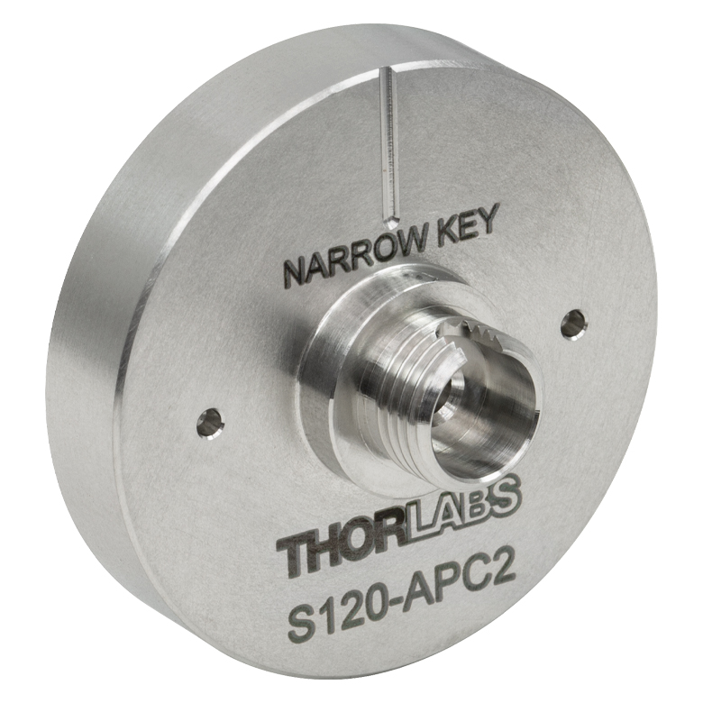
- Internally SM1-Threaded (1.035"-40) Disks with FC/PC, FC/APC, SMA, ST®*/PC, SC/PC, LC/PC, or Ø2.5 mm Ferrule Receptacle
- Light-Tight Construction when used with SM1 Lens Tubes
These Fiber Adapters can be used with many of our avalanche photodetectors above. Note that we do not recommend using fiber connector adapters alone to couple light onto the APD401A2(/M), APD430A2(/M), and APD430A(/M) avalanche photodetectors due to the small size of their sensors. To achieve high coupling efficiency, a fiber collimation package, focusing lens, and X-Y translator should be used. See the Fiber Coupling tab for details.
The FC/PC and FC/APC adapters are available in narrow or wide key versions; for details on narrow versus wide key connectors, please see our Intro to Fiber tutorial.
The FC/APC adapters have two dimples in the front surface that allow them to be tightened with the SPW909 or SPW801 spanner wrench. The dimples do not go all the way through the disk so that the adapter can be used in light-tight applications when paired with SM1 lens tubes.
The S120-25 ferrule adapter is designed without a locking connector mechanism and accepts fiber patch cables with Ø2.5 mm ferrules for quick measurements with photodetectors or power sensors.
| Item # | S120-FC2 | S120-FC | S120-APC2a | S120-APCa | S120-SMA | S120-ST | S120-SC | S120-LC | S120-25 |
|---|---|---|---|---|---|---|---|---|---|
| Adapter Image (Click the Image to Enlarge) |
 |
 |
 |
 |
 |
 |
 |
 |
 |
| Fiber Connector Type | FC/PC, 2.0 mm Narrow Key |
FC/PC, 2.2 mm Wide Key |
FC/APC, 2.0 mm Narrow Key |
FC/APC 2.2 mm Wide Key |
SMA | ST/PC | SC/PCb | LC/PC | Ø2.5 mm Ferrule |
| Threading | Internal SM1 (1.035"-40) | ||||||||
*ST® is a registered trademark of Lucent Technologies, Inc.
Part Number | Description | Price | Availability |
|---|---|---|---|
S120-FC2 | FC/PC Fiber Adapter Cap with Internal SM1 (1.035"-40) Threads, Narrow Key (2.0 mm) | $46.33 | Today |
S120-FC | FC/PC Fiber Adapter Cap with Internal SM1 (1.035"-40) Threads, Wide Key (2.2 mm) | $46.33 | Today |
S120-APC2 | FC/APC Fiber Adapter Cap with Internal SM1 (1.035"-40) Threads, Narrow Key (2.0 mm) | $36.18 | Today |
S120-APC | Customer Inspired! FC/APC Fiber Adapter Cap with Internal SM1 (1.035"-40) Threads, Wide Key (2.2 mm) | $36.18 | Today |
S120-SMA | SMA Fiber Adapter Cap with Internal SM1 (1.035"-40) Threads | $46.33 | 3 weeks |
S120-ST | ST/PC Fiber Adapter Cap with Internal SM1 (1.035"-40) Threads | $46.33 | Today |
S120-SC | SC/PC Fiber Adapter Cap with Internal SM1 (1.035"-40) Threads | $58.21 | Today |
S120-LC | LC/PC Fiber Adapter Cap with Internal SM1 (1.035"-40) Threads | $58.21 | Today |
S120-25 | Customer Inspired! Ø2.5 mm Ferrule Adapter Cap with Internal SM1 (1.035"-40) Threads | $46.33 | Today |