Manual 360° Rotation Stage with Two Hard Stops

- Continuous 360° Rotation with Two User-Positionable Hard Stops
- Ø2" Mounting Platform with an Array of Tapped Holes
- Precise, Submicron Repeatability (<15 µrad)
QRP02
Application Idea
Ø1" Mirror Mounted in a
FMP1 Lens Mount on a
TR2 Post, PH1.5 Post
Holder, and QRP02
Rotation Stage. Light
can be Reflected in Two
Repeatable Directions

Please Wait
Features
- 360° Rotation with Two User-Positionable Hard Stops
- Quick, Highly Repeatable Rotation of an Optic or Optical Device
- Load Capacity: 75 lb (34 kg) with Stage Mounted on a Horizontal Surface
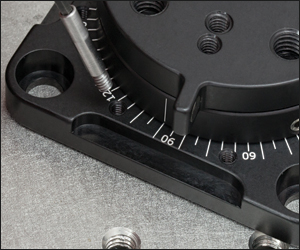
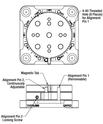
The QRP02(/M) Rotation Stage offers 360° of continuous manual rotation with two user-positionable hard stops. The first hard stop can be positioned to coincide with any of the eight 4-40-tapped holes located at 45° intervals in the base. The stop's position is set using a threaded alignment pin that is secured with a 5/64" (2 mm) hex key. The second hard stop is an alignment pin attached to a rotating section under the mounting platform. It can be positioned anywhere along the 360° range of motion and locked into place by tightening the setscrew to the left of the dowel using a 5/64" (2 mm) hex key.
The rotation platform is secured to the hard stops by a double-sided magnetic tab and can be moved between them with <15 µrad repeatability. The stage's base has an engraved scale indicating the angular position of the alignment pins and mounting platform. The scale is engraved in 5° intervals, marked every 30° by a number directly over its corresponding tick mark.
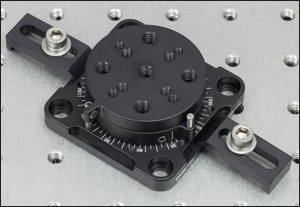
The Ø2" (Ø50.8 mm) mounting platform includes an array of 1/4"-20 (M6), 8-32 (M4), and 6-32 (M4) tapped holes for mounting optomechanical components, including our PM3 and PM4 clamping arms. The base is equipped with 1/4" (M6) counterbores on 2" (50 mm) centers to enable optical table or breadboard mounting. Additionally, the rotation mount's base can be mounted at any angle of rotation using the side relief cuts and our CL6 or CL8 clamps, allowing for the arbitrary positioning of both hard stops (see photo below, right).
This stage offers a 75 lb (34 kg) load capacity when mounted on a horizontal surface. When mounted on a vertical surface, a torque up to 2.5 lb·ft (3.4 N·m) can be applied about an axis orthogonal to the rotation axis. In testing, a 20 lb (9.1 kg) load was placed 1.5" (38 mm) from the mounting surface, at the center of the platform. If the load also applies a torque about the rotational axis, the magnetic tab must be secured above an alignment pin instead of below.

Click to Enlarge
Hard Stop 1 can be Screwed into One of Eight Holes at Various Locations on the Base, while Hard Stop 2 is Continuously Adjustable Using the Setscrew on the Lower Rotating Section

Click to Enlarge
The QRP02(/M) can be Mounted to an Optical Table or Breadboard at an Arbitrary Angle, Using our CL6 (Shown) or CL8 Clamping Arms, for Full Control of the Position of the First Stop
| Specifications | ||
|---|---|---|
| Item # | QRP02 | QRP02/M |
| Rotation Range | 360°, Continuous | |
| Hard Stop 1 Locationsa | 20°, 25°, 65°, 70°, 110°, 115°, 155°, 160°, 200°, 205°, 245°, 250°, 290°, 295°, 335°, or 340° on Engraved Scale |
|
| Hard Stop 2 Location | Continuously Variable | |
| Repeatability | <15 µrad | |
| Wobble | <0.002" (0.051 mm) | |
| Horizontal Load Capacityb | 75 lb (34 kg) | |
| Vertical Mounting Torque Capacityc | 2.5 lb·ft (3.4 N·m) | |
| Platform Dimension | Ø2" (Ø50.8 mm), Circular | |
| Platform Mounting Holes | 1/4"-20 (5 Places) 8-32 (4 Places) 6-32 (4 Places) |
M6 x 1.0 (5 Places) M4 x 0.7 (8 Places) |
| Base Dimensions | 2.55" x 2.55" | 64.8 mm x 64.8 mm |
| Base Mounting Holes | 1/4" Counterbore (4 Places) on 2" Centers |
M6 Counterbore (4 Places) on 50 mm Centers |
| Eight 8-32 Threaded Holes for Positioning the Threaded Dowel Pin Hard Stop | ||
| Posted Comments: | |
Scott Milligan
(posted 2021-03-24 15:58:27.087) This is an interesting product that is unfortunately hamstrung by easily fixable design flaws. The cockamamie 6.78 degree offset between the counterbored mounting holes & the position of the rotating part's index mark when registered against any of the fixed 8 locations for stop#1 makes it impossible to use these stops to reference any of the 4 cardinal "compass" points (i.e. 0, 90, 180, & 270 degrees) without the index mark reading 6.78 degrees off these points. Given the rectilinear hole pattern most common on breadboards & other "stuff" you might want to integrate into an assembly, this situation practically forbids use in any assembly where a technician is asked to follow a work instruction that requires accurate reading of this stage's angular position wrt to another rectilinear coordinate system. 2 possible fixes include: 1. (preferred) 8 additional 4_40 tapped holes to position a fixed stop such that when registered against the stop, the index mark coincides with either the 0, 90, 180, or 270 orientation wrt to the base mounting hole pattern), or (less desirable) 2. the addition of a rotating scale pattern that the user can set and then lock down, such as you implement in several of your rotation stages for 1" & 2" optical components. My preferred solution (#1) would likely require rethinking the geometry of the four areas in the base that are relieved to enable external clamps to grab the base, however, with the angular offset problem fixed, I expect the need for external clamping would mostly disappear. Just my $0.02. asundararaj
(posted 2021-03-30 10:15:45.0) Thank you for your feedback on the QRP02. I have forwarded your suggestions to our internal product forum, where we may consider these improvements for a future product. Kyle Meaker
(posted 2019-10-05 16:44:55.097) Our research group owns one of these, and we are curious if there is a maximum temperature allowance for this product. I could not see any information online. Are there any plastic elements maybe inside that could be damaged?
Thank you so much,
-Kyle YLohia
(posted 2019-10-07 11:32:48.0) Hello Kyle, thank you for contacting Thorlabs. While the QRP02 does contain PTFE, the limiting factor for the maximum temperature of this unit will be the grease used (Apiezon M). This grease has a typical working range of 10-30 C (50-86 F). This device is designed to be used in a controlled lab environment, which is typically operated within this temperature range. |
Rotation Mount and Stage Selection Guide
Thorlabs offers a wide variety of manual and motorized rotation mounts and stages. Rotation mounts are designed with an inner bore to mount a Ø1/2", Ø1", or Ø2" optic, while rotation stages are designed with mounting taps to attach a variety of components or systems. Motorized options are powered by a DC Servo motor, 2 phase stepper motor, piezo inertia motor, or an Elliptec™ resonant piezo motor. Each offers 360° of continuous rotation.
Manual Rotation Mounts
| Rotation Mounts for Ø1/2" Optics | |||||||
|---|---|---|---|---|---|---|---|
| Item # | MRM05(/M) | RSP05(/M) | CRM05 | PRM05(/M)a | SRM05 | KS05RS | CT104 |
| Click Photo to Enlarge |
 |
 |
 |
 |
 |
 |
 |
| Features | Mini Series | Standard | External SM1 (1.035"-40) Threads |
Micrometer | 16 mm Cage-Compatible | ±4° Kinematic Tip/Tilt Adjustment Plus Rotation | Compatible with 30 mm Cage Translation Stages and 1/4" Translation Stagesb |
| Additional Details | |||||||
| Rotation Mounts for Ø1" Optics | ||||||||
|---|---|---|---|---|---|---|---|---|
| Item # | RSP1(/M) | LRM1 | RSP1D(/M) | DLM1(/M) | CLR1(/M) | RSP1X15(/M) | RSP1X225(/M) | PRM1(/M)a |
| Click Photo to Enlarge |
 |
 |
 |
 |
 |
 |
 |
 |
| Features | Standard | External SM1 (1.035"-40) Threads |
Adjustable Zero | Two Independently Rotating Carriages | Rotates Optic Within Fixed Lens Tube System |
Continuous 360° Rotation or 15° Increments |
Continuous 360° Rotation or 22.5° Increments |
Micrometer |
| Additional Details | ||||||||
| Rotation Mounts for Ø1" Optics | ||||||
|---|---|---|---|---|---|---|
| Item # | LM1-A & LM1-B(/M) |
CRM1T(/M) | CRM1LT(/M) | CRM1PT(/M) | KS1RS | K6XS |
| Click Photo to Enlarge |
  |
 |
 |
 |
 |
 |
| Features | Optic Carriage Rotates Within Mounting Ring | 30 mm Cage-Compatiblea | 30 mm Cage-Compatible for Thick Opticsa |
30 mm Cage-Compatible with Micrometera |
±4° Kinematic Tip/Tilt Adjustment Plus Rotation | Six-Axis Kinematic Mounta |
| Additional Details | ||||||
| Rotation Mounts for Ø2" Optics | |||||||
|---|---|---|---|---|---|---|---|
| Item # | RSP2(/M) | RSP2D(/M) | PRM2(/M) | LM2-A & LM2-B(/M) |
LCRM2A(/M) | KS2RS | K6X2 |
| Click Photo to Enlarge |  |
 |
 |
  |
 |
 |
 |
| Features | Standard | Adjustable Zero |
Micrometer | Optic Carriage Rotates Within Mounting Ring | 60 mm Cage-Compatible | ±4° Kinematic Tip/Tilt Adjustment Plus Rotation | Six-Axis Kinematic Mount |
| Additional Details | |||||||
| Rotation Drive Mechanism and Adjustment Range | Manual, 360° Continuous | Coarse: Manual, 360° Continuous; Fine: ±7° Micrometer |
Manual, 360° Continuous | ||||
| Optic Mounting | Internally SM2-Threaded Carriage | Internal SM2 Threads in LM2-A |
Internally SM2-Threaded Carriage | ||||
| Maximum Accepted Optic Thickness | 0.51" (13 mm) | 0.54" (13.7 mm) | 0.48" (12.2 mm) | 0.46" (11.7 mm) | 0.52" (13.2 mm) | 0.47" (12 mm) | 0.53" (13.4 mm) |
| Post Mounting | 8-32 (M4) Tap | 8-32 (M4) Tap in LM2-B | 8-32 (M4) Tap | Four Counterbores for 8-32 (M4) Cap Screws | Six Counterbores for 8-32 (M4) Cap Screws | ||
| Cage System Compatibility | N/A | Four 4-40 (M3) Taps on Rotation Dial with 60 mm Spacing |
N/A | Four Bores for Ø6 mm Cage Rods with 60 mm Spacing |
N/A | N/A | |
Manual Rotation Stages
| Manual Rotation Stages | ||||||
|---|---|---|---|---|---|---|
| Item # | RP005(/M) | PR005(/M) | MSRP01(/M) | RP01(/M) | RP03(/M) | QRP02(/M) |
| Click Photo to Enlarge |
 |
 |
 |
 |
 |
 |
| Features | Standard | Two Hard Stops | ||||
| Additional Details | ||||||
| Manual Rotation Stages | ||||||
|---|---|---|---|---|---|---|
| Item # | XRNR1(/M) | XRR1(/M) | PR01(/M) | CR1(/M) | XYR1(/M) | OCT-XYR1(/M) |
| Click Photo to Enlarge |
 |
 |
 |
 |
 |
 |
| Features | Fine Rotation Adjuster and 2" Wide Dovetail Quick Connect |
Fine Rotation Adjuster and 3" Wide Dovetail Quick Connect |
Fine Rotation Adjuster and SM1-Threaded Central Aperture |
Fine Pitch Worm Gear | Rotation and 1/2" Linear XY Translation | |
| Additional Details | ||||||
Motorized Rotation Mounts and Stages
| Motorized Rotation Mounts and Stages with Central Clear Apertures | |||||
|---|---|---|---|---|---|
| Item # | DDR25(/M) | PDR1C(/M) | PDR1(/M) | PDR1V(/M) | PDXR1(/M) |
| Click Photo to Enlarge |
 |
 |
 |
 |
 |
| Features | Compatible with SM05 Lens Tubes, 16 mm Cage System, & 30 mm Cage System |
Compatible with 16 mm Cage System |
Compatible with SM05 Lens Tubes & 30 mm Cage System |
Vacuum-Compatible; Also Compatible with SM05 Lens Tubes & 30 mm Cage System |
Compatible with SM05 Lens Tubes & 30 mm Cage System |
| Additional Details | |||||
| Motorized Rotation Mounts and Stages with Central Clear Apertures | |||||
|---|---|---|---|---|---|
| Item # | K10CR1(/M) | PRM1Z8(/M)a | DDR100(/M) | ELL14 | HDR50(/M) |
| Click Photo to Enlarge |
 |
 |
 |
 |
 |
| Features | Compatible with SM1 Lens Tubes & 30 mm Cage System | Compatible with SM1 Lens Tubes, 16 mm Cage System, 30 mm Cage System |
Compatible with SM1 Lens Tubes, Open Frame Design for OEM Applications |
Compatible with SM2 Lens Tubes |
|
| Additional Details | |||||
| Motorized Rotation Mounts and Stages with Tapped Platforms | ||
|---|---|---|
| Item # | PRMTZ8(/M)a | ELL18(/M)b |
| Click Photo to Enlarge |
 |
 |
| Features | Tapped Mounting Platform for Mounting Prisms or Other Optics | Tapped Mounting Platform, Open Frame Design for OEM Applications |
| Additional Details | ||
 Products Home


 Rotation Stage with Two Hard Stops