 Products Home / Active Optical Devices / Gain Chips / SAF Gain Chips in High Heat Load Ø9 mm TO Can Package
SAF Gain Chips in High Heat Load Ø9 mm TO Can Package
- GaAs Gain Chips in High Heat Load Ø9 mm TO Can Package
- Three Models Available with Wavelengths Centered at 780, 840, or 1040 nm
- Ultra-Low Reflectance at Angled Facet
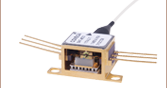
SAF851T
SAF Gain Chip in Ø9 mm TO Can,
840 nm CWL


Please Wait
| Key Specificationsa | |||
|---|---|---|---|
| Item # | SAF781T | SAF851T | SAF1064T |
| ASE Center Wavelength | 780 nm | 840 nm | 1040 nm |
| Angled Facet Reflectivity | 0.01% (Max) | ||
| Normal Facet Reflectivity | 90% | ||
| Integrated ASE Power (CW) | 110 mW | 85 mW | 75 mW |
| Optical 10 dB Bandwidthb | 14 nm | 40 nm | 50 nm |
| Lateral Beam Exit Angle | 19.5° ± 2.0° | ||
| Pin Code | E | ||
| Drawingc |  |
||
| SAF Gain Chips |
|---|
| Chip in Ø9 mm TO Can |
| 780, 840, and 1040 nm CWL |
| Half-Butterfly Assembly |
| CWLs from 1220 nm to 1900 nm |
| Chip on Submount |
| 1220 nm CWL |
| 1320 nm CWL |
| 1450 nm CWL |
| 1528 - 1568 nm (C-Band) 1568 - 1608 nm (L-Band) |
| 1650 nm CWL |
Features
- Gain Chips in Ø9 mm TO Can Package
- Three Models Available with Center Wavelengths (CWLs):
- 780 nm with 14 nm 10 dB Bandwidth
- 840 nm with 40 nm 10 dB Bandwidth
- 1040 nm with 50 nm 10 dB Bandwidth
- 19.5 Degree Beam Exit Angle
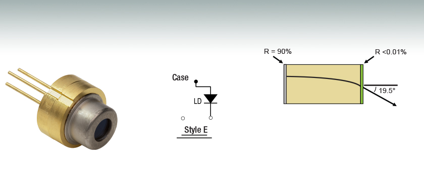
Thorlabs' Single Angled Facet (SAF) Gain Chips are comprised of a high-power, GaAs active waveguide gain element in a High Heat Load (HHL) Ø9 mm TO can package with pin code E. The gain chips have a curved ridge waveguide that reduces the reflection on one end of the chip so that it is not normally incident to the chip facet. This, in combination with an AR coating on that facet, virtually eliminates back reflections that can create unwanted feedback into the laser cavity. The SAF design has a low modal reflectance of up to 0.01% at the angled facet and an optimum reflectance of 90% at the normal facet. This unique combination of ridge waveguide laser design and low angled facet reflectance makes the SAF ideal for use as the gain component in high-power tunable external cavity lasers (ECLs). The SAF gain chips are available with center wavelengths at 780, 840, or 1040 nm. These wavelengths are suitable for ECLs with applications for atom cooling and trapping or atomic clocks.
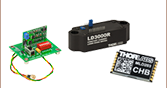
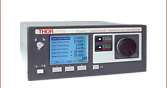
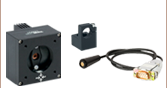
The SAF gain chips can be mounted to the LDM90(/M) Laser Diode Mount and driven by the ITC4001 benchtop controller for temperature controlled operation.
Note: the SAF gain chips are not intended to be used as Amplified Spontaneous Emission (ASE) sources as this will significantly decrease their lifetime. For more information on using the SAF gain chip in an external cavity laser, see the ECL Tutorial tab.
| Specificationsa,b | |||
|---|---|---|---|
| Item # | SAF781T | SAF851T | SAF1064T |
| ASE Center Wavelength | 780 nm | 840 nm | 1040 nm |
| Angled Facet Reflectivity | 0.01% (Max) | ||
| Normal Facet Reflectivity | 90% | ||
| Operating Current (Typ. / Max) |
300 mA / 350 mA | 650 mA / 700 mA | 400 mA / 450 mA |
| Forward Voltage | 2.0 V | 2.2 V | 1.6 V |
| L-I-V Data (Click Icon for Plot) |
Raw Data |
Raw Data |
Raw Data |
| Integrated ASE Power (CW) | 110 mW | 85 mW | 75 mW |
| Optical 3 dB Bandwidthc | 7.5 nm | 22 nm | 28 nm |
| Optical 10 dB Bandwidthd | 14 nm | 40 nm | 50 nm |
| Output Spectrum (Click Icon for Plot) |
Raw Data |
Raw Data |
Raw Data |
| Gain Ripple (Peak - Peak) | 1 dB (Max) | ||
| Transverse Far Field (FWHM)e | 16° | 14° | 14° |
| Lateral Far Field (FWHM)e | 7° | 6° | 8° |
| Far Field Measurement Data (Click Icon for Plot) |
Raw Data |
Raw Data |
Raw Data |
| Near Field Lateral Emission | 3 µm | ||
| Near Field Vertical Emission | 1 µm | ||
| Chip Length | 3 mm | ||
| Lateral Beam Exit Angle | 19.5° ± 2.0° | ||
- Specifications are given at a case temperature TCASE = 25 °C. The operating temperature range is TOP = 15 °C - 30 °C. Specifications are typical unless stated otherwise; full specifications and drawings can found by clicking on the red Docs (
 ) icon below.
 - These Single Active Facet (SAF) gain chips are meant to be used in external cavity lasers. Product lifetime will be significantly reduced by using it in an Amplified Spontaneous Emission mode.
- Width of the ASE Spectrum at 3 dB Below the Peak
- Width of the ASE Spectrum at 10 dB Below the Peak
- The far field measurement measures the light divergence angle from the gain chip. A Transverse measurement is when the measurement slit is at a 0° orientation to measure the horizontal cone of light, while a Lateral measurement is when the slit is rotated 90° to measure the vertical cone of light.
External Cavity Diode (ECL) Lasers: Tunable Wavelength and Narrow Bandwidth
Two elements are required for a laser to operate: (1) an active gain medium that amplifies the optical signal and (2) a feedback mechanism to provide sustained laser oscillation. In a Fabry-Perot laser, two mirrors, having reflection coefficients of r1 and r2 (power reflectance R1 = r12 and R2 = r22), respectively, provide feedback for the optical field, as shown in Figure 1.
Figure 1: Fabry-Perot Laser Structure
The round-trip gain for the optical field within a cavity of length L can be expressed as:
Equation 1: Round-Trip Gain for Optical Field
where g and αi are the gain and internal loss coefficients, respectively, λ is the vacuum wavelength, neff is the effective refractive index, and L is the cavity length. Solving for unity results in the threshold amplitude and phase conditions:
Equation 2: The Amplitude Condition
Equation 3: The Phase Condition
where αm is defined as the mirror loss and N is a running integer index representing the mode number.
In a semiconductor (diode) laser, the gain medium is excited by injecting a current into the junction region of a forward-biased diode. The high concentration of electrons and holes in the engineered quantum-well junction of a semiconductor laser makes it possible to create the population inversion required for optical gain.
When the gain medium is a semiconductor material, a Fabry-Perot cavity can be created by the Fresnel optical reflections at the cleaved facets of the chip. The junction is effectively a waveguide that extends from one facet to the other. An uncoated "as-cleaved" facet perpendicular to the waveguide has a reflectivity of R ~ 30%. However, the maximum output power of the device can be optimized by modifying the reflectance of the facets with optical coatings. Maximum power for a Fabry-Perot laser diode is typically achieved with a high-reflectivity (HR) coating on the back facet and a low-reflectivity (LR) coating on the front facet.
The emission spectrum of the Fabry-Perot laser diode device will be dependent on the injection current. When biased below threshold with g > αi , the emission spectrum consists of a broad series of peaks corresponding to the longitudinal modes of the Fabry-Perot cavity defined by the phase equation. Lasing does not occur until the injection current is increased to the point where g = αi + αm. The lasing wavelength is determined by the longitudinal mode that first achieves the threshold condition. The output spectrum does not always collapse into a single lasing wavelength but can consist of a narrow spectrum of longitudinal modes.
Figure 2: Gain Curve of a Fabry-Perot Laser
This is particularly true for InP-based Fabry-Perot lasers, which typically have an optical bandwidth of 5 to 10 nm. GaAs-based devices can operate in a single longitudinal mode, depending on wavelength and output power. They typically have an output bandwidth <2 nm.
A typical 850 nm laser diode with a length of around 300 µm and a group index around 4 will have a longitudinal mode spacing of 0.3 nm, which is similar to a 1 mm long 1550 nm laser diode. Changing the length or refractive index of the cavity, for example by heating or cooling the laser diode, will shift the whole comb of modes and consequently the output wavelength.
Laser Linewidth
The linewidth of a semiconductor laser single longitudinal lasing mode (FWHM) is given by the modified Schawlow and Townes formula that incorporates the Henry linewidth enhancement factor αH [1]:
Equation 4: Schawlow-Townes-Henry Laser Linewidth
where hv is the photon energy, vg is the group velocity, nsp is the population inversion factor, and Pout is the single-facet output power. This equation describes the spectral broadening of the laser linewidth due to phase and amplitude fluctuations caused by the unavoidable addition of spontaneous emission photons to the coherent lasing mode. These so-called quantum noise fluctuations define a lower limit on the laser linewidth, which may be masked by larger noise fluctuations caused by mechanical/acoustic vibration or thermal variation.
Extending the length of the cavity will decrease αm (see Eq. 2), which reduces the linewidth. This can be understood by viewing the quantum noise-limited linewidth (see Eq. 4) as being proportional to the ratio of the number of spontaneous emission photons in the lasing mode. Increasing the cavity length both reduces the number of spontaneous emission photons (by decreasing the "cold-cavity" spectral width of each longitudinal mode) and increases the total number of photons in the cavity for a fixed output power. This is why the cavity length term appears twice in the Schallow-Townes equation.
A single-frequency distributed feedback (DFB) diode laser with cavity of 0.3 mm will typically have an emission linewidth on the order of 1 to 10 MHz. Increasing the length of the cavity to 3 cm, for example, will narrow the emission linewidth by a factor of more than 100. It has been shown [2] that the linewidth of the emission from an extended cavity semiconductor lasers can be reduced to <1 kHz.
Single Wavelength Operation and Tuning
For many applications, it is desirable to have a single longitudinal mode (single frequency) laser, to be able to adjust the lasing wavelength, or both. To accomplish this, a wavelength-selective feedback element external to the semiconductor laser chip can be used to select the lasing wavelength. Proper operation of this external cavity laser (ECL) requires suppression of the intrinsic optical feedback from the semiconductor chip Fabry-Perot cavity so that it does not interfere with the external feedback. The gain chip's Fabry-Perot cavity effect can be reduced by applying an antireflection (AR) optical coating to one chip facet.
Figure 3: External Cavity Operation Based on a Gain Chip
At a minimum, the chip facet reflectance (R1) should be 20 dB less than the external feedback (Rext); that is, R1 < 10-2 x Rext [3]. Even with the AR coating, the residual reflection from the AR-coated Fabry-Perot gain chip facet often limits the stability, output power, and spectral quality of the ECL, especially if the laser is tunable. To further reduce the reflection at the chip facet, the combination of an angled waveguide and an AR coating can be used to effectively remove most of the feedback from the internal chip Fabry-Perot cavity [4]. This single-angled-facet (SAF) gain chip provides a superior structure for ECLs, in particular broadband tunable ECLs.
Figure 4: Single-Angled-Facet Gain Chip
External Cavity Laser Design
There are numerous approaches for implementing an external cavity semiconductor laser [3]. The first consideration for most approaches is the choice of a wavelength-selective feedback element. One of the most common feedback elements is a diffraction grating, which can be used as the feedback element in both single-frequency and broadly tunable external cavity lasers.
When the collimated output of the gain chip is incident on a diffraction grating at angle θ with respect to the grating surface normal and perpendicular to the grating lines, the diffracted beams exit the grating at an angle θ' determined by the grating equation:
Equation 5: Grating Equation
Here, n is the order of diffraction, λ is the diffracted wavelength, and d is the grating constant (the distance between grooves). For n > 0, the diffraction grating will spatially separate a polychromatic incident beam by diffracting the beam at an angle θ', which is wavelength dependent. Once the spectral content of the gain chip is spatially separated, a variety of means can be employed to selectively reflect light with a specific wavelength back into the gain medium.
Littrow ECL Configuration
One of the simplest approaches is to use a Littrow configuration where the diffraction grating is oriented so that the first-order diffraction is retroreflected back into the gain chip [i.e., θ = θ' in Eq. (5) above]:
Equation 6: Grating Equation, Littrow Configuration
The laser output power can be taken from the zero-order reflection of the grating, which is often done because it minimizes the number of optical elements required to construct the ECL (a collimating lens and the diffraction grating).
Wavelength tuning is accomplished by rotating the diffraction grating, which varies the wavelength of light that is reflected back into the waveguide. When the diffraction grating (grating constant), collimation lens, and cavity length are chosen so that only one longitudinal mode is reflected back to the gain chip within the acceptance angle of the waveguide, the external cavity laser will produce a signle frequency laser spectrum. Note that the selection of collimation lens is important because it affects the amount of grating area that is illuminated as well as the focused spot size coupling back into the semiconductor gain chip. One of the disadvantages of this configuration is that the angle of the zero-order output beam changes as the wavelength is tuned. However, this problem can be avoided if the output of the ECL is emitted from the normal facet of the SAF gain chip. In this configuration, the reflectance of the SAF normal facet is typically reduced to R ~ 10% and a grating is chosen that efficiently diffracts light into the order being used to create the ECL to maximize the output power of the laser.
Figure 5: Littrow External Cavity Laser
Littman-Metcalf ECL Configuration
Another common ECL implementation is the Littman-Metcalf configuration, which uses an additional adjustable mirror to select the feedback wavelength [5]. The double-pass of the diffraction grating at an increased angle of incidence results in an external cavity that has better wavelength selectivity. As a result, the output beam of a Littman-Metcalf ECL typically as a narrower linewidth than a similar laser built using a Littrow configuration. In the Littman-Metcalf configuration, the output beam of the laser is typically the zero-order reflection from the diffraction grating, since the propagation direction remains fixed as the wavelength is tuned. In this case, the SAF normal facet is coated with a high-reflective (HR) coating, typically >90%, in order to minimize the losses in the ECL, which maximizes the output power.
Figure 6: Littman-Metcalf External Cavity Laser
For some applications it may still be desirable to use the normal facet of the SAF chip as the output coupler of the laser. For these applications, a low reflection coating on the normal facet of the SAF gain chip would be required in order to maximize the output power of the laser.
One drawback to the Littman-Metcalf design is that the internal losses are higher than in the Littrow configuration, and hence, the output power of the laser is typically lower. The increase in internal losses are mainly due to the loss of the zero-order beam reflected from the tuning mirror and the increased loss due to the decrease in the efficiency of the grating when used to reflect light at a large angle of incidence.
Innovative ECL Design
The innovative design of an SAF gain chip is ideal for use in external cavity lasers because it virtually eliminates the unwanted feedback from the intracavity facet of the gain chip. Thorlabs offers SAF chips with both low- and high-reflectivity coatings on the normal facet in order to support a wide variety of external cavity configurations. For information on custom coatings that optimize the performance of a particular external cavity laser configuration, please contact Tech Support.
References
(1) Henry, C. H., "Theory of the Linewidth of Semiconductor Lasers." IEEE J. of Quantum Electron QE-18, 259 (1982).
(2) Wyatt, R., Cameron, K. H., and Matthews, M. R. "Tunable Narrow Line External Cavity Lasers for Coherent Optical Communication Systems." Br. Telecom. Technol. J. 3, 5 (1985).
(3) Zorabedian, P. "Tunable External Cavity Semiconductor Lasers." Tunable Lasers Handbook Ed. Duarte, F. J. New York, Academic, 1995. Chapter 8.
(4) Heim, P. J. S., Fan, Z. F., Cho, S.-H., Nam, K., Dagenais, M., Johnson, F. G., and Leavitt, R. "Single-angled-facet Laser Diode for Widely Tunable External Cavity Semiconductor Lasers with High Spectral Purity." Electron. Lett. 33, 1387 (1997).
(5) Littman, M. G. and Metcalf, H. J. "Spectrally narrow pulsed dye laser without beam expander." Appl. Opt. 17, 2224 (1978).
| Posted Comments: | |
| No Comments Posted |