 Products Home / Fiber Components / Collimation / Coupling / Reflective Collimators / Adjustable Focus Reflective Collimators, Protected Silver Coating
Adjustable Focus Reflective Collimators, Protected Silver Coating

- Adjustable Collimators/Couplers with a 15 mm Reflected Focal Length
- Maximum Fiber NA without Clipping the Beam: 0.30
- Free From Chromatic Aberrations
- FC/PC, FC/APC, or SMA Connector
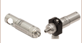
RCF15P-P01
FC/PC Connector
RCF15S-P01
SMA Connector
Application Idea
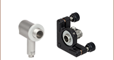
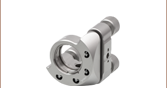
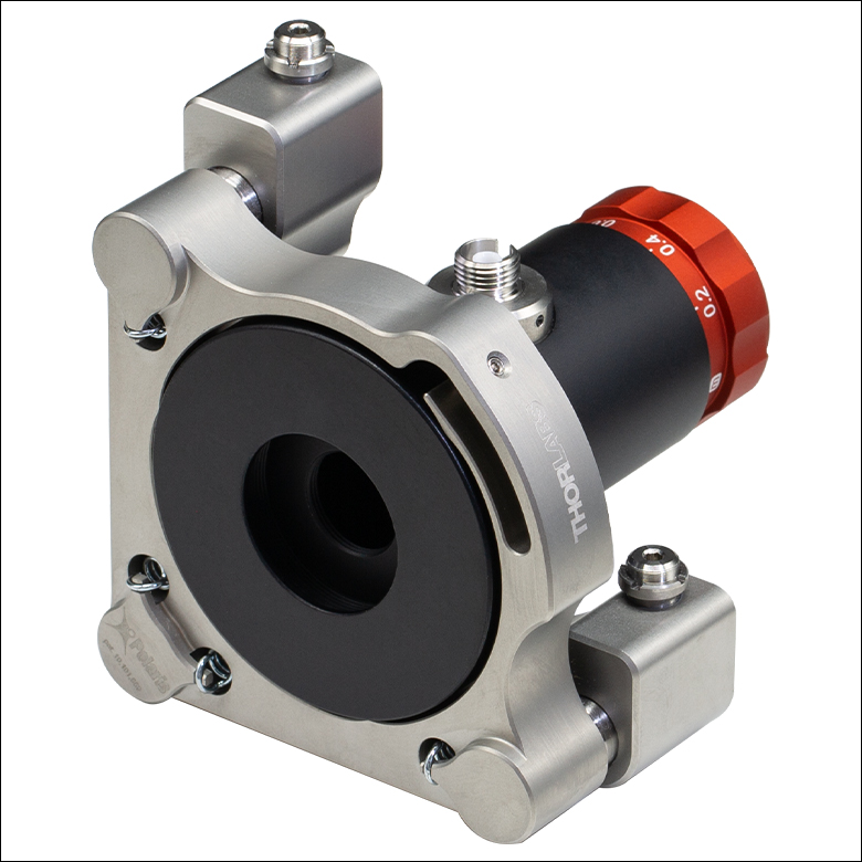
The RCF15A-P01 Collimator is mounted in an SM1TC Lens Tube Clamp. See the Mounting Options Tab for more details.
RCF15A-P01
FC/APC Connector


Please Wait

Click to Enlarge
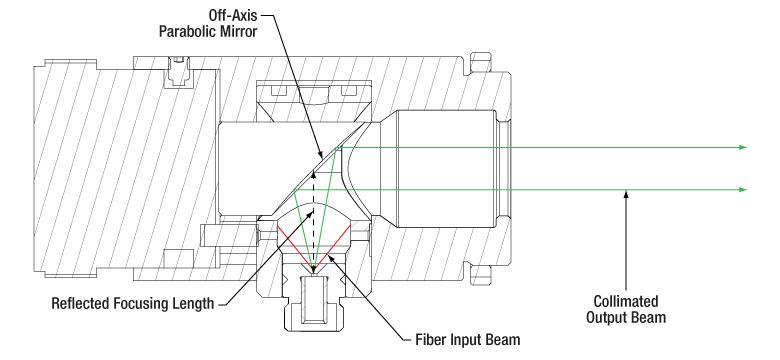
Collimating Light from an Optical Fiber
(Can also be Used in Reverse for Coupling Light into Multimode or Single Mode Fiber)

Click to Enlarge
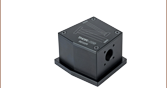
The collimator includes a red adjustment knob, which controls the position of the fiber input. The focusing distance scale (in meters) allows the beam to be tuned from diverging to focused; see the Diagrams tab for details. The Ø1.20" (30.5 mm) housing outer diameter matches that of our Ø1" SM1 lens tubes.
Features
- Free From Chromatic Aberrations for Collimation Over the Mirror's Reflection Band (450 nm - 20 µm)
- Ideal for Coupling Polychromatic Light into Multimode or Single Mode Fiber
- 15 mm Reflected Focal Length
- Ø11.0 mm Clear Aperture
- Adjustable Focusing Distance from -2.2 m to 0.15 m
- Maximum Fiber NA without Clipping the Beam: 0.30
- Ø1.20" Outer Diameter Provides Compatibility with Slip Rings and Tube Clamps
- External SM1 Threading and Internal SM05 Threading for Compatibility with Ø1" and Ø1/2" Lens Tubes
Thorlabs' Protected Silver Adjustable Focus Reflective Collimators are based on 90° off-axis parabolic (OAP) mirrors. These protected silver mirrors, unlike lenses, have focal lengths that remain constant at any wavelength and excellent reflectivity within the
To optimize light collimation from an individual fiber or light coupling into a single mode or multimode fiber, these collimators feature an adjustable fiber-to-OAP distance. The collimated beam position, denoted by ∞ on the focusing distance scale, sets the fiber-to-OAP distance to the reflected focal length (RFL) of the mirror (see the figure to the right); the beam focus can be adjusted around this position by turning the red adjustment knob on the collimator housing. The full focusing distance range goes from -2.2 m to 0.15 m, which are the negative and positive focusing distance limits, respectively. When changing the focusing distance, the fiber position is moved; see the Diagrams tab for more information about producing a focused or diverging beam from these adjustable collimators.
At infinite conjugate ratios, the OAP mirror achieves diffraction-limited imaging. Due to the principles of focusing with an off-axis parabola, optical aberrations are introduced when changing the focusing distance; see the Insights tab for more information on the unique properties of OAP mirrors. These adjustable reflective collimators can also be used for collimator-to-collimator coupling over long distances, allowing the free-space beam to be manipulated prior to entering the second collimator, which can be useful in long-distance-communication applications.
Common applications include collimating polychromatic light emitted from a single-mode or multimode optical fiber and coupling polychromatic collimated light into single-mode or multimode fiber. When collimating light from a single-mode or multimode patch cable, the fiber numerical aperture (NA) should be ≤0.30 to avoid clipping light on the housings of the collimators. Note that in general, light from a multimode fiber cannot be well collimated. For more information on how to optimize collimation of light from an optical fiber, please see the Collimation Tutorial tab.
Scattering from the mirror surface is minimal
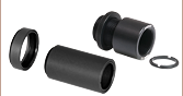
The adjustable reflective collimator housings have an internal SM05 (0.535"-40) and external SM1 (1.035"-40) threading, allowing for easy integration with lens tube systems. The adjustable reflective collimators are equipped with a locking ring to lock them to any SM1 threaded parts they are connected to; if a replacement is required, we recommend our SM1NT1 locking ring. For applications where it is difficult to reach the locking ring by hand, the 1¼" end of the SPW502 spanner wrench can engage with the slots in the locking ring. Please see the Mounting Options tab for more details.
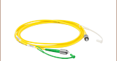
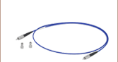
Fiber Patch Cables for Reflective Collimators
Thorlabs offers single mode, polarization-maintaining, or multimode fiber optic patch cables for both coupling and collimating applications. If you cannot find the appropriate stock patch cable for your application, custom-connectorized patch cables with same-day shipping are also available.
The RCF15A-P01 and RCF15P-P01 collimators are constructed with 2.2 mm wide-key FC/APC or FC/PC connectors, respectively. The wide key accepts both wide and narrow key connectors; however, using a narrow-key connector in a wide-key slot will allow the connector to rotate slightly in the mating sleeve. Collimation packages with ports for 2.2 mm wide key FC/PC or FC/APC connectors have tightly toleranced ceramic sleeves that provide excellent pointing repeatability, allowing the user to easily adjust the focus distance and replace the fiber without the need for large realignments. Please note that careful alignment is needed when mating a narrow key polarization maintaining fiber with the collimator's wide key receptacle.
Thorlabs also offers UV-Enhanced Aluminum coating reflective collimators for high reflectivity in the 250 - 450 nm wavelength range or compact reflective silver collimators with a protected silver coating for easy integration into cage systems. We also offer a variety of other collimators, including large-beam achromatic fiber collimators, zoom fiber collimators, fixed focus triplet collimators, and FiberPort adjustable collimation packages, which are well suited for use with a wide range of wavelengths. See the Collimator Guide tab for our complete line of collimation and coupling options.
For adjustable focus reflective collimators with UV-Enhanced Aluminum (-F01), Protected Gold (-M01), or Unprotected Gold (-M03) mirrors, please contact Tech Sales.
| Specifications | |||
|---|---|---|---|
| Item # | RCF15P-P01 | RCF15A-P01 | RF15S-P01 |
| Fiber Connector | FC/PC | FC/APC | SMA |
| Clear Aperture | Ø11.0 mm | ||
| Typical Collimated Beam Diameter (1/e2)a |
Ø3.1 mm (SM400 at 450 nm) Ø2.8 mm (SM600 at 633 nm) Ø3.3 mm (780HP at 780 nm) Ø2.9 mm (SMF-28-J9 at 1550 nm) Ø4.7 mm (SM1950 at 2 µm) |
||
| Full Angle Beam Divergenceb | 0.011° (SM400 at 450 nm) 0.016° (SM600 at 633 nm) 0.018° (780HP at 780 nm) 0.040° (SMF-28-J9 at 1550 nm) 0.031° (SM1950 at 2 µm) |
||
| Maximum Fiber Numerical Aperture (NA) |
0.30 | ||
| Focusing Distance Rangec | -2.2 m to 0.15 m | ||
| Fiber Adjustment Distancec | 2.2 mm | ||
| Reflected Focal Length (RFL) | 15.0 mm | ||
| Parent Focal Length (PFL)d | 7.5 mm | ||
| Coating | Protected Silver | ||
| Wavelength Range | 450 nm - 20 µm | ||
| Reflectance (Avg., AOI = 45°) | >97% (450 nm - 2 µm) >95% (2 - 20 µm) |
||
| Surface Quality | 40-20 Scratch-Dig | ||
| Surface Roughness | <100 Å RMS | ||
| Reflected Wavefront Error |
<λ/4 RMS at 633 nm | ||
| Pointing Errore | <10 mrad | <10 mrad | - |

Click to Enlarge
Excel Spreadsheet with Raw Data for Protected Silver
The blue shaded region in the graph denotes the range over which we guarantee the specified reflectance.

Click to Enlarge
Diagram of Beam Collimated by the OAP Mirror in the Reflective Collimator
Adjustment of the Collimator
When the adjustable collimator is at the position marked by ∞ on the focusing distance scale, the off-axis parabolic (OAP) reflective collimator results in a collimated beam; see the diagram in the Overview tab for details. Minor adjustments around this position can be used to optimize the collimation of light from (or coupling of light into) an individual fiber. Additionally, the output beam from the RCF15x-P01 collimators can be adjusted through the focusing distance range (-2.2 m to 0.15 m), from diverging from behind the mirror to focusing in front of the mirror. Below are ray diagrams for a positive focusing distance (Focusing Beam) and a negative focusing distance (Diverging Beam).

Click to Enlarge
Diverging Beam: From the collimated position, indicated by the ∞ symbol on the focal distance scale, rotating the red adjustment knob towards negative focal distances moves the fiber in the indicated direction. The result is a beam that is diverging from a point behind the OAP mirror, with the distance indicated in negative meters on the scale.

Click to Enlarge
Focusing Beam: From the collimated position, indicated by the ∞ symbol on the focal distance scale, rotating the red adjustment knob towards positive focal distances moves the fiber in the indicated direction. The result is a beam that is focused in front of the OAP mirror, with the distance indicated in positive meters on the scale.
Mounting the Collimator
The black anodized section of the RCF15x-P01 housing has an outer diameter of Ø1.20", which matches the outer diameter of our Ø1" (SM1) lens tubes. As a result, these collimators can be easily mounted to a post using an SM1RC(/M) slip ring or an SM1TC tube clamp, as shown in the image below, or integrated into our optical cage systems. For example, they can be inserted into a 30 mm cage system using a CP36 cage plate.
If tip/tilt adjustment is required, we recommend using a Polaris® Mirror Mount to mount the collimator; please note that mounting adapters may be needed. For example, mounting the collimator into a

Click to Enlarge RCF15A-P01 Collimator Secured in an SM1TC Lens Tube Clamp
Lens Tube Integration
The RCF15x-P01 collimator housing features both internal SM05 (0.035"-40) and external SM1 (1.035"-40) threading on the free-space end for compatibility with Thorlabs' lens tubes and other optical components. See the images below for examples of an adjustable collimator attached to a Ø1/2" or Ø1" lens tube.


Collimating Light Tutorial
Click to Enlarge
Click Here for Theoretical Data
This data is calculated for our SM400, SM600, 780HP, and
SMF-28-J9 single mode fibers and our RCF15x-P01 adjustable reflective collimators.
Collimating Light from a Single Mode Fiber with an Adjustable Reflective Collimator
When collimating light from single-mode fibers, the Adjustable Reflective Fiber Collimators produce beams with large waist diameters and low divergence. The graph to the right illustrates the theoretical 1/e2 beam diameter as a function of propagation distance for four different SM fiber-coupled laser wavelengths using our adjustable reflective collimators. The effect of changing the fiber or the wavelength can be estimated using the theoretical approximations below.
Theoretical Approximation of the Divergence Angle of an Output Beam
The divergence angle can be approximated theoretically using the formula below as long as the light emerging from the fiber has a Gaussian intensity profile. Therefore, the formula works well for single mode (SM) fibers.
The full divergence angle of the output beam using an SM fiber in degrees is approximated by

where θSM is the divergence angle of the beam after collimation, MFD is the mode field diameter of the fiber, and RFL is the reflected focal length of the reflective collimator. The MFD and RFL must have the same units in this equation.
Example Calculation:
When the RCF15A-P01 collimator (RFL = 15 mm) is used with the P3-630A-FC-1 SM patch cable (MFD = 4.3 µm), the divergence angle is:
θSM ≈ (0.0043 mm / 15 mm) x (180 / 3.1416) ≈ 0.016° or 0.29 mrad.
Theoretical Approximation of the Output Beam Diameter
The 1/e2 output beam diameter can be found using the approximation

where λ is the wavelength of light being used, MFD is the mode field diameter of the fiber, and RFL is the reflected focal length of the reflective collimator.
Example Calculation:
When the RCF15A-P01 collimator (RFL = 15 mm) is used with the P3-630A-FC-1 SM patch cable (MFD = 4.3 µm) at λ = 633 nm = 0.633 µm, the output beam diameter is:
d = 4 x 0.633 µm x [15 mm / (3.1416 x 4.3 µm)] = 2.8 mm.
Click to Enlarge
Click Here for Theoretical Data
This data is calculated for our FG010LDA, FG025LJA, and FG105LVA multimode fibers and our RCF15x-P01 adjustable reflective collimators, set to collimate the output beam.
Collimating Light from a Multimode Fiber with an Adjustable Reflective Collimator
The geometrical ray model can be used to describe the collimation of light from multimode (MM) fibers. Consider an off-axis point on the MM core. Light from this point will generate a collimated beam at an angle to the optical axis of the off-axis parabolic (OAP) mirror. Superimposing beams from all points on the MM core results in an output beam with significant divergence, unlike the output from the SM fiber described above. The graphs to the right show the calculated beam diameter as a function of distance from the adjustable reflective couplers for three different MM fibers.
Theoretical Approximation of the Divergence Angle of an Output Beam
The full angle divergence of an output beam generated from a MM fiber can be approximated with the help of the reflected focal length (RFL) of the reflective collimator and the core diameter of the MM fiber as follows:
where θMM is the divergence angle of the beam after collimation, calculated in degrees.
Example Calculation:
When the RCF15S-P01 collimator (RFL = 15 mm) is used with the M96L01 MM patch cable (Core Diameter = 105 µm), the full divergence angle is:
θMM ≈ (0.105 mm / 15 mm) x (180 / 3.1416) ≈ 0.40° or 7.0 mrad.
Theoretical Approximation of the Output Beam Diameter
Based on the ray model, the beam diameter as a function of distance from the reflective collimator and NA can be approximated with the following relation:

The equation above shows that the beam diameter is more strongly affected by the numerical aperture (NA) of the fiber close to the reflecting mirror, whereas the core diameter more strongly affects the beam diameter far from the collimator.
The graphs to the right illustrate the approximated beam diameter as a function of the distance from the collimator for three different MM fibers (FG010LDA, FG025LJA, FG105LVA), all with an NA = 0.1. These results are independent of wavelength and connector type, but depend on the reflected focal length of the collimator.
Using MM fibers with NAs >0.30 for the RCF15x-P01 (e.g., NA = 0.39 or 0.50) will cause light to be clipped by the housing of the collimators before it reaches the OAP mirror (as shown in the images below). Therefore, when collimating light from a MM patch cable, the fiber NA should be ≤0.30, to avoid clipping light on the housing.
Aside from all these considerations based on simple paraxial optics, please keep in mind that a perfect off-axis parabola can only collimate light without aberrations from a point source, located at the mirror's focal point. The further the point is away from the optical axis or the larger the core of the MM fiber, the larger the introduced optical aberrations for the off-axis rays of the extended source. Finally, the off-axis points of the extended source cannot be perfectly collimated. The effects of aberrations can, however, be minimized by increasing the reflected focal length of the reflective collimator or by increasing the wavelength.

Click to Enlarge
Low-NA Fiber: The green lines indicate the envelope of the fiber input beam as it diverges and is collimated by the OAP mirror.
Click to Enlarge
High-NA Fiber: The red lines indicate the envelope of the fiber input beam that is clipped by the collimator housing. The green lines show the portion of the beam that is collimated by the OAP mirror.

Insights into Off-Axis Parabolic Mirrors
Scroll down to read about the unique properties of off-axis parabolic (OAP) mirrors and how to take advantage of them:
- Focus Collimated Light / Collimate Light from a Point Source
- Benefits of Pairing OAP Mirrors
- Mounting and Aligning an OAP Mirror
Click here for more insights into lab practices and equipment.
Focus Collimated Light / Collimate Light from a Point Source
Parabolic and off-axis parabolic (OAP) mirrors will only provide the expected well-collimated beam or diffraction-limited focal spot when the correct beam type is incident along the proper axis. This due to the parabolic shape of these mirrors' reflective surfaces, which are not symmetric around their focal points.
Parabolic vs. Off-Axis Parabolic Mirrors
The reflective surface of an OAP mirror is a section of the parent parabola that is not centered on the parent's optical axis (Figure 1). A conventional parabolic mirror is illustrated in Figure 2.
The optical axis of an OAP mirror is parallel to, but displaced from the optical axis of the parent parabola. The focal point of the OAP mirror coincides with that of the parent parabola.
The focal axis of the OAP mirror passes through the focal point and the center of the OAP mirror. The focal and optical axes of an OAP mirror are not parallel. In contrast, these axes coincide for parabolic mirrors whose reflective surfaces are centered on optical axis of the parent parabola.
Focus Collimated Light
If a parabolic or OAP mirror is being used to focus a beam of collimated light to a diffraction-limited point, the light must be directed along the mirror's optical axis (Figures 1 and 2).
Collimated light that is not directed parallel to the optical axis will not focus to a unique point (Figure 3).
Thorlabs recommends against directing collimated light along the focal axis of OAP mirrors, or along any direction that is not parallel to the optical axis, since the light will not focus to a diffraction-limited spot.
Collimate Light from a Point Source
To obtain highly collimated light from a point source, the point source should be located at the mirror's focal point.
Light from a point source will be poorly collimated if the point source is placed along the OAP mirror's optical axis, or anywhere else that is not the focal point.
An OAP mirror can also be used to collimate a spherical wave, if its origin coincides with the focal point of the mirror.

Click to Enlarge
Figure 3: When the collimated beam is not directed along the mirror's optical axis, the mirror does not provide a diffraction-limited spot. Instead, the focal region is spread out.

Click to Enlarge
Figure 2: When the collimated beam is parallel to the optical axis of a parabolic or OAP mirror, the light focuses to a diffraction-limited spot.

Click to Enlarge
Figure 1: The focal and optical axes of an OAP mirror do not coincide and are not parallel.
Date of Last Edit: Dec. 4, 2019
Benefits of Pairing OAP Mirrors
Click to Enlarge
Figure 5: A pair of OAP mirrors can be used to couple light out of one fiber and into another. This provides access to the beam when it is necessary to insert bulk optics into the optical path. Due to the small dimension of the fiber core, light emitted from the fiber end face is similar to a point source.

Click to Enlarge
Figure 4: A pair of OAP mirrors can be used in imaging applications, and/or to relay a beam across a distance.
Relay an Image
A single OAP mirror is not recommended for finite conjugate imaging applications, when neither light beam is collimated, but a pair of OAP mirrors can successfully be used for this purpose. An example setup is illustrated in Figure 4.
The dual OAP configuration facilitates the process of adjusting the distance between mirrors. The leg of collimated light is also convenient for inserting filters and other optical elements into the beam. Another benefit is that distance between the two mirrors can be adjusted to move the focal point across the source and/or target planes without disturbing the alignment of the system.
Provide Access to the Beam in a Fiber Network
A pair of OAP mirrors can be used to create a free-space leg in an optical fiber system, which is one way to provide access to the light beam. The illustration in Figure 5 shows an example of this configuration, which can be useful when filters or other bulk optics need to be inserted into the beam path. The length of the free-space leg can be adjusted without disturbing alignment.
When setting up this system, the fibers' end faces must be aligned so that their cores coincide with the source and target focal points, respectively. The collimated beam paths of both mirrors should be co-linear and completely overlapping.
This configuration is the basis for fiber optic filter / attenuator mounts.
Date of Last Edit: Dec. 4, 2019
Mounting and Aligning an OAP Mirror
Click to Enlarge
Figure 7: When using an OAP mirror to collimate a point source, a shear plate interferometer placed in the output beam can facilitate the alignment process.
Click to Enlarge
Figure 6: The shape of the OAP mirror's reflective profile matches a section of the parent parabola that is not centered on the focal point. Due to this, the OAP's reflective surface is not rotationally symmetric. When mounting the mirror, care should be taken to ensure the mirror does not rotate around its optical axis.
OAP mirrors are not rotationally symmetric. This is due to their reflective surfaces being taken from sections of the parent parabola curve located away from the focal point (Figure 6).
Due the asymmetry of the reflector, when an OAP mirror rotates, the position of its focal point also rotates. Since this could negatively impact the performance of an optical system, the mirror should be fixed so that the reflective surface cannot rotate around its optical axis.
The optical performance of the mirror is also sensitive to alignment drift with respect to the other five degrees of freedom. One way to protect against alignment drift is to use a fixed, rather than a kinematic, mount.
Using a shear plate interferometer can be helpful when aligning an OAP mirror to an input point source. The shear plate interferometer should intercept the output beam (Figure 7), to assess its collimation quality. Alignment is optimized when the quality of the collimated beam is optimized.
Date of Last Edit: Dec. 4, 2019
Fiber Collimator Selection Guide
Click on the collimator type or photo to view more information about each type of collimator.
| Type | Description | |
|---|---|---|
| Fixed FC, APC, or SMA Fiber Collimators | 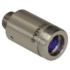 |
These fiber collimation packages are pre-aligned to collimate light from an FC/PC-, FC/APC-, or SMA-terminated fiber. Each collimation package is factory aligned to provide diffraction-limited performance for wavelengths ranging from 405 nm to 4.55 µm. Although it is possible to use the collimator at detuned wavelengths, they will only perform optimally at the design wavelength due to chromatic aberration, which causes the effective focal length of the aspheric lens to have a wavelength dependence. |
| Air-Spaced Doublet, Large Beam Collimators |  |
For large beam diameters (Ø5.3 - Ø8.5 mm), Thorlabs offers FC/APC, FC/PC, and SMA air-spaced doublet collimators. These collimation packages are pre-aligned at the factory to collimate a laser beam propagating from the tip of an FC or SMA-terminated fiber and provide diffraction-limited performance at the design wavelength. |
| Triplet Collimators |  |
Thorlabs' High Quality Triplet Fiber Collimation packages use air-spaced triplet lenses that offer superior beam quality performance when compared to aspheric lens collimators. The benefits of the low-aberration triplet design include an M2 term closer to 1 (Gaussian), less divergence, and less wavefront error. |
| Achromatic Collimators for Multimode Fiber |  |
Thorlabs' High-NA Achromatic Collimators pair a meniscus lens with an achromatic doublet for high performance across the visible to near-infrared spectrum with low spherical aberration. Designed for use with high-NA multimode fiber, these collimators are ideal for Optogenetics and Fiber Photometry applications. |
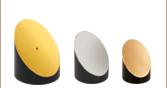
| Reflective Collimators | 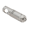 |
Thorlabs' metallic-coated Reflective Collimators are based on a 90° off-axis parabolic mirror. Mirrors, unlike lenses, have a focal length that remains constant over a broad wavelength range. Due to this intrinsic property, a parabolic mirror collimator does not need to be adjusted to accommodate various wavelengths of light, making them ideal for use with polychromatic light. Our reflective collimators are ideal for collimating single mode fiber but are not recommended for coupling into single mode fiber. We also offer a compact version of the protected-silver-coated reflective collimators that is directly compatible with our 16 mm cage system. |
| FiberPorts |  |
These compact, ultra-stable FiberPort micropositioners provide an easy-to-use, stable platform for coupling light into and out of FC/PC, FC/APC, or SMA terminated optical fibers. It can be used with single mode, multimode, or PM fibers and can be mounted onto a post, stage, platform, or laser. The built-in aspheric or achromatic lens is available with five different AR coatings and has five degrees of alignment adjustment (3 translational and 2 pitch). The compact size and long-term alignment stability make the FiberPort an ideal solution for fiber coupling, collimation, or incorporation into OEM systems. |
| Adjustable Fiber Collimators |  |
These collimators are designed to connect onto the end of an FC/PC, FC/APC, or SMA connector and contain an AR-coated aspheric lens. The distance between the aspheric lens and the tip of the fiber can be adjusted to compensate for focal length changes or to recollimate the beam at the wavelength and distance of interest. |
| Achromatic Fiber Collimators with Adjustable Focus |  |
Thorlabs' Achromatic Fiber Collimators with Adjustable Focus are designed with an effective focal length (EFL) of 20 mm, 40 mm, or 80 mm, have optical elements broadband AR coated for one of three wavelength ranges, and are available with FC/PC, FC/APC, or SMA905 connectors. A four-element, air-spaced lens design produces superior beam quality (M2 close to 1) and less wavefront error when compared to aspheric lens collimators. These collimators can be used for free-space coupling into a fiber, collimation of output from a fiber, or in pairs for collimator-to-collimator coupling over long distances, which allows the beam to be manipulated prior to entering the second collimator. |
| Zoom Fiber Collimators | 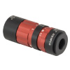 |
These collimators provide a variable focal length between 6 and 18 mm, while maintaining the collimation of the beam. As a result, the size of the beam can be changed without altering the collimation. This universal device saves time previously spent searching for the best suited fixed fiber collimator and has a very broad range of applications. They are offered with FC/PC, FC/APC, or SMA905 connectors with three different antireflection wavelength ranges to choose from. |
| Single Mode Pigtailed Collimators | 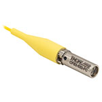 |
Our single mode pigtailed collimators come with one meter of fiber, consist of an AR-coated aspheric lens pre-aligned with respect to a fiber, and are collimated at one of eight wavelengths: 532 nm, 633 nm, 780 nm, 850 nm, 1030 nm, 1064 nm, 1310 nm, or 1550 nm. Although it is possible to use the collimator at any wavelength within the coating range, the coupling loss will increase as the wavelength is detuned from the design wavelength. |
| Polarization Maintaining Pigtailed Collimators | 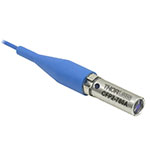 |
Our polarization maintaining pigtailed collimators come with one meter of fiber, consist of an AR-coated aspheric lens pre-aligned with respect to a fiber, and are collimated at one of five wavelengths: 633 nm, 780 nm, 980 nm, 1064 nm, or 1550 nm. Custom wavelengths and connectors are available as well. A line is engraved along the outside of the housing that is parallel to the fast axis. As such, it can be used as a reference when polarized light is launched accordingly. Although it is possible to use the collimator at any wavelength within the coating range, the coupling loss will increase as the wavelength is detuned from the design wavelength. |
| GRIN Fiber Collimators | 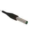 |
Thorlabs offers gradient index (GRIN) fiber collimators that are aligned at a variety of wavelengths from 630 to 1550 nm and have either FC terminated, APC terminated, or unterminated fibers. Our GRIN collimators feature a Ø1.8 mm clear aperture, are AR-coated to ensure low back reflection into the fiber, and are coupled to standard single mode or graded-index multimode fibers. |
| GRIN Lenses | 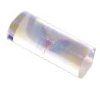 |
These graded-index (GRIN) lenses are AR coated for applications at 630, 830, 1060, 1300, or 1560 nm that require light to propagate through one fiber, then through a free-space optical system, and finally back into another fiber. They are also useful for coupling light from laser diodes into fibers, coupling the output of a fiber into a detector, or collimating laser light. Our GRIN lenses are designed to be used with our Pigtailed Glass Ferrules and GRIN/Ferrule sleeves. |
| Posted Comments: | |
| No Comments Posted |

 Zoom
Zoom| Item #a | RFLb | Connector | Max Fiber NAc | Typical Collimated Beam Diameter (1/e2)d | Full Angle Beam Divergencee |
|---|---|---|---|---|---|
| RCF15P-P01 | 15 mm | 2.2 mm Wide-Key FC/PC | 0.30 | Ø3.1 mm (SM400 at 450 nm) Ø2.8 mm (SM600 at 633 nm) Ø3.3 mm (780HP at 780 nm) Ø2.9 mm (SMF-28-J9 at 1550 nm) Ø4.7 mm (SM1950 at 2 µm) |
0.011° (SM400 at 450 nm) 0.016° (SM600 at 633 nm) 0.018° (780HP at 780 nm) 0.040° (SMF-28-J9 at 1550 nm) 0.031° (SM1950 at 2 µm) |
| RCF15A-P01 | 2.2 mm Wide-Key FC/APC | ||||
| RCF15S-P01 | SMA |