 Products Home
C-Band Tunable Bandpass Filter
- Digital Tunable Bandpass Filter for 1527 nm to 1567 nm
- 50 GHz Dense Wavelength Division Multiplexing (DWDM) ITU Grid
- ≤0.77 nm (96.1 GHz) Passband Width at -20 dB
- >27 dB Non-Adjacent Isolation
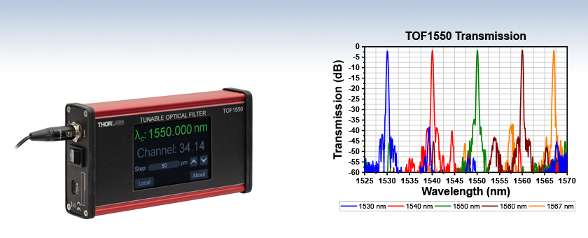
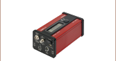
TOF1550
Tunable Bandpass Filter,
1527 - 1567 nm


Please Wait
| Key Specifications | |
|---|---|
| Wavelength Tuning Range | 1527 - 1567 nm |
| Passband Width @ -1 dBa | ≥0.12 nm (15.0 GHz) |
| Passband Width @ -3 dBa | ≥0.21 nm (26.2 GHz) |
| Passband Width @ -20 dBa | ≤0.77 nm (96.1 GHz) |
| Insertion Lossa,b,c | <3.5 dB (2.5 dB Typical) |
| Polarization Dependent Loss | <0.3 dB |
| Non-Adjacent Isolationa | ≥27 dB |
| Maximum Input Power | 300 mW (24.78 dBm) |
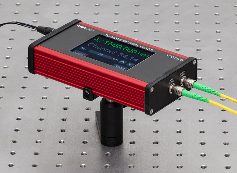
Click to Enlarge
The TOF1550 is mounted to an optical table using an ECM325 mounting clamp.

Click to Enlarge
The functions of the TOF1550 digital tunable bandpass filter is shown above. An input optical signal is input using the narrow-key FC/APC fiber port and is then filtered based on the setting given using the touchscreen on the device or using the remote commands. The filtered signal is then output through another narrow-key FC/APC fiber port. Please see the manual for more operation information.
Features
- Tunable, Gaussian Bandpass Filter for C-Band Operation
- FC/APC Narrow Key (2.0 mm) Fiber Input and Output
- Ideal for DWDM ITU Grid Channel Spacing Applications
- <3.5 dB (2.5 dB Typical) Insertion Loss at 1550 nm
- Remote Operation Through USB Type-C Port
Applications
- Dense Wavelength Division Multiplexing (DWDM)
- Spectral Response Characterization
- Out-of-Band ASE Suppression
- Receiver Testing
The TOF1550 is a tunable Gaussian bandpass filter designed to operate with telecommunication C-band (1527 - 1567 nm) signals on a dense wavelength division multiplexing (DWDM) ITU grid. The center wavelength of the bandpass can be tuned to any position within the operating wavelength range by selecting either the wavelength directly or a channel on the ITU grid. If multiple DWDM channels are input into the filter, only the selected channel will be transmitted while all others will be blocked. If a broadband optical signal is input, only the passband around the center wavelength will be transmitted. The filter can also be used in a laboratory or production environment as an aid in optical signal selection, monitoring and diagnosis of an optical communication system, characterizing spectral response of detection or amplification systems, or an amplified stimulated emission filter to enhance a laser's signal-to-noise ratio.
Passband Tuning
The TOF1550 touchscreen allows the target center wavelength "λc" to be specified either directly within the operating range of 1527 - 1567 nm or by selecting a desired ITU grid channel from 14 to 63. This passband can then be adjusted using the "Step" up and down arrows. The step size for the wavelength or channel can be adjusted in steps as small as 1 pm or 0.01 channel (1 GHz), respectively, though the tuning resolution of the TOF1550 filter passband is <12 pm (1.5 GHz). See the Operation tab for more details on adjusting the filter parameters and the Specs and Graphs tabs for more details on the tuning parameters and performance.
Remote Operation
In addition to operating the TOF1550 bandpass filter using the touchscreen interface on the device, the USB Type-C port and the included corresponding USB cable can be used to remotely operate the filter. See the Operation tab for more details. The TOF1550 filter will appear as a serial (COM) port which can be accessed and run using the supplied driver. Any computer that can communicate via a serial port can operate the filter remotely. See the Software tab for more details.
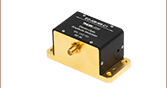
Mounting Options
The TOF1550 tunable bandpass filter utilizes Thorlabs' EEET6011 compact aluminum housing enabling the device to be mounted using the compatible mounting equipment such as the ECM125 and ECM325 (shown above) aluminum clamps. The housing features silicone rubber bezels to provide surfaces with higher friction than the aluminum housing and protect the faces from scratches.

Click for Details
Mechanical Drawing of the TOF1550 Tunable Banpass Filter
| Item # | TOF1550 |
|---|---|
| Wavelength Tuning Range | 1527 - 1567 nm |
| Passband Width @ -1 dBa | ≥0.12 nm (15.0 GHz) |
| Passband Width @ -3 dBa | ≥0.21 nm (26.2 GHz) |
| Passband Width @ -20 dBa | ≤0.77 nm (96.1 GHz) |
| Insertion Lossa,b,c | <3.5 dB (2.5 dB Typical) |
| Polarization Dependent Loss | <0.3 dB |
| Non-Adjacent Isolationa | ≥27 dB |
| Chromatic Dispersion (Absolute) | <10 ps/nm |
| Polarization Mode Dispersion | <0.1 ps |
| Wavelength Tuning Resolution | <12 pm (1.5 GHz) |
| Wavlength Setting Error (Absolute) | <32 pm (4 GHz) |
| Wavelength Setting Repeatability | ±8 pm (1 GHz) |
| Wavelength Temperature Dependence (Absolute) | <1 pm/°C |
| Return Loss | >40 dB |
| Maximum Input Optical Power | 300 mW (24.78 dBm) |
| Fiber Specifications | |
| Fiber Type | SMF-28 |
| Fiber Length | 70 ± 10 cm |
| Environmental Condition | |
| Operating Temperature | -5 to 65 °C |
| Storage Temperature | -40 to 85 °C |
| Operating Relative Humidity | 5 to 85% |
| Storage Relative Humidity | 5 to 95% |
Sample performance plots for the TOF1550 tunable bandpass filter are shown below.

Click to Enlarge
Click for Raw Data
The plot above shows a detailed view of the transmission of the TOF1550 filter at 1550 nm. The transmission is found by measuring the insertion loss.
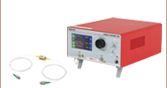
Click to Enlarge
Click for Raw Data
The plot above shows the transmission of the TOF1550 tunable filter with the passband tuned to five different center wavelengths: 1530, 1540, 1550, 1560, and 1567 nm. The transmission is found by measuring the insertion loss.
Click to Enlarge
The plot above shows the wavelength setting error over the entire tuning range for the TOF1550 bandpass filter.
Click to Enlarge
The passband width of the TOF1550 versus wavelength measured for -1, -3, and -20 dB attenuation.
Click to Enlarge
The plot above shows the wavelength setting error over the entire tuning range for the TOF1550 bandpass filter.

Click to Enlarge
Shown above is the insertion loss of the TOF1550 filter over the operating wavelength range defined at the peak of the filter transfer function.
The TOF1550 tunable bandpass filter can be controlled directly via the touchscreen interface on the front panel or through remote control using the provided USB Type-C cable and port on the side of the device.
Contents
Click to Enlarge
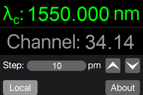
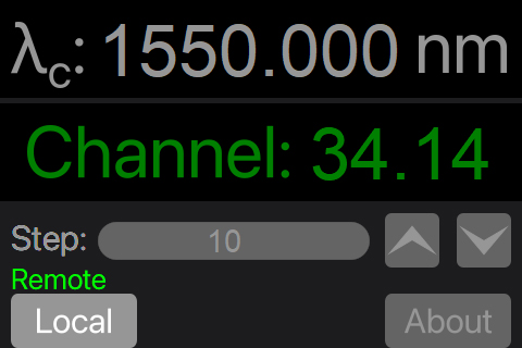
Figure 2: The main display screen above shows the channel selected as the main tuning parameter. The wavelength displayed will correspond to the channel center wavelength.
Click to Enlarge
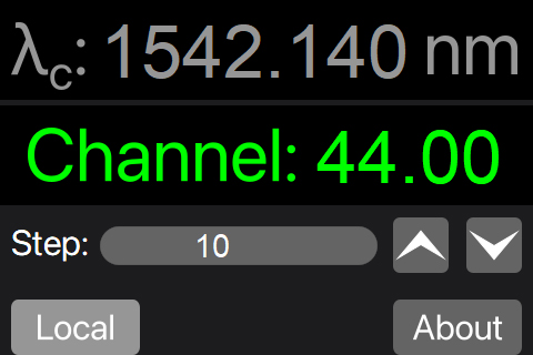
Figure 1: The main display screen above shows the center wavelength selected as the tuning parameter.
Click to Enlarge
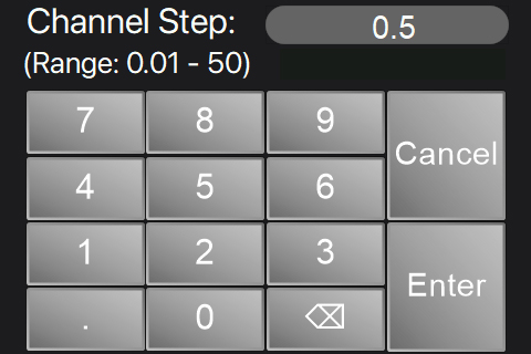
Figure 4: The channel step selection screen is shown above. The channel step increment can be set from 0.01 to 50.
Click to Enlarge
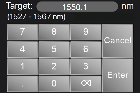
Figure 3: The target wavelength screen allows for the center wavelength of the passband to be directly input.
Touchscreen Operation
The touchscreen interface of the TOF1550 tunable bandpass filter can be used to directly select either the target center wavelength “λc” or the Channel of the desired passband. The center wavelength corresponds to the center of the passband while the channel number corresponds to the DWDM ITU grid channel numbers. See the table below for a list of channels based on a 100 GHz spaced ITU grid.
The main screen of the interface, shown in Figures 1 and 2, displays the center wavelength, channel, and step value settings. The selected parameter (“λc” or “Channel”) will be highlighted in green while the units for the “Step” value will change between pm or channel number depending on the selected parameter as shown in Figures 1 and 2. Pressing the up and down arrows in the step row will increase or decrease the selected parameter by the step amount. The target center wavelength and wavelength step, or channel and channel step can be input manually when either “λc” or "Channel" are active by selecting the desired row.
Figure 3 shows the screen where the center wavelength can be manually input. The center wavelength can be adjusted from 1527 nm to 1567 nm with a minimum resolution of 1 pm. Likewise, the channel number can be input from 14 to 63 with a minimum increment of 0.01.
The step setting for either center wavelength or channel number can be input only when either the center wavelength or the channel number is selected. Figure 4 shows an image of the channel step setting screen, which is edited when the Channel row is selected as shown in Figure 2. The Channel step can be adjusted between the range of 0.01 and 50 with an increment of 0.01 (1 GHz) while the wavelength step can be adjusted from 1 pm to 50 000 pm with a minimum increment of 1 pm.
The table below shows the channels in the 100 GHz spaced ITU grid that are within the operating range of the TOF1550 filter along with the corresponding frequency in GHz and wavelength in nm.
| ITU Grid Channelsa | ||||||||
|---|---|---|---|---|---|---|---|---|
| Channel # | Frequency (GHz) | Wavelength (nm) | Channel # | Frequency (GHz) | Wavelength (nm) | Channel # | Frequency (GHz) | Wavelength (nm) |
| 14 | 191 400 | 1566.31 | 31 | 193 100 | 1552.52 | 48 | 194 800 | 1538.98 |
| 15 | 191 500 | 1565.50 | 32 | 193 200 | 1551.72 | 49 | 194 900 | 1538.19 |
| 16 | 191 600 | 1564.68 | 33 | 193 300 | 1550.92 | 50 | 195 000 | 1537.40 |
| 17 | 191 700 | 1563.86 | 34 | 193 400 | 1550.12 | 51 | 195 100 | 1536.61 |
| 18 | 191 800 | 1563.05 | 35 | 193 500 | 1549.32 | 52 | 195 200 | 1535.82 |
| 19 | 191 900 | 1562.23 | 36 | 193 600 | 1548.52 | 53 | 195 300 | 1535.04 |
| 20 | 192 000 | 1561.42 | 37 | 193 700 | 1547.72 | 54 | 195 400 | 1534.25 |
| 21 | 192 100 | 1560.61 | 38 | 193 800 | 1546.92 | 55 | 195 500 | 1533.47 |
| 22 | 192 200 | 1559.79 | 39 | 193 900 | 1546.12 | 56 | 195 600 | 1532.68 |
| 23 | 192 300 | 1558.98 | 40 | 194 000 | 1545.32 | 57 | 195 700 | 1531.90 |
| 24 | 192 400 | 1558.17 | 41 | 194 100 | 1544.53 | 58 | 195 800 | 1531.12 |
| 25 | 192 500 | 1557.36 | 42 | 194 200 | 1543.73 | 59 | 195 900 | 1530.33 |
| 26 | 192 600 | 1556.56 | 43 | 194 300 | 1542.94 | 60 | 196 000 | 1529.55 |
| 27 | 192 700 | 1555.75 | 44 | 194 400 | 1542.14 | 61 | 196 100 | 1528.77 |
| 28 | 192 800 | 1554.94 | 45 | 194 500 | 1541.35 | 62 | 196 200 | 1527.99 |
| 29 | 192 900 | 1554.13 | 46 | 194 600 | 1540.56 | 63 | 196 300 | 1527.22 |
| 30 | 193 000 | 1553.33 | 47 | 194 700 | 1539.77 | - | - | - |
Remote Operation and Driver Download
Click to Enlarge
Figure 5: The wavelength, channel, and step buttons are grayed out while the TOF1550 is being operated remotely.
Driver Download
Driver Version 1.0 (September 16, 2024)
Click the link below to download the driver for the TOF1550 tunable filter.
The TOF1550 tunable filter can be operated remotely through the USB Type-C port on the side panel of the device using the included USB cable. When in remote operation mode, the tuning parameters on the touchscreen will be inaccessible and dimmed as shown in Figure 5 to the right. The TOF1550 filter will appear as a virtual serial COM port on the connected PC. The tuning parameters can be adjusted by sending commands with syntax modeled on the IEEE 488.2 Standard Commands for Programmable Instruments (SCPI). The serial port configuration should be set to the parameters given below:
- Baud Rate: 115 200
- Bit: 8
- Parity: None
- Stop Bits: 1
- Flow Control: None
Please refer to the manual for more information on remotely operating the TOF1550 tunable bandpass filter.
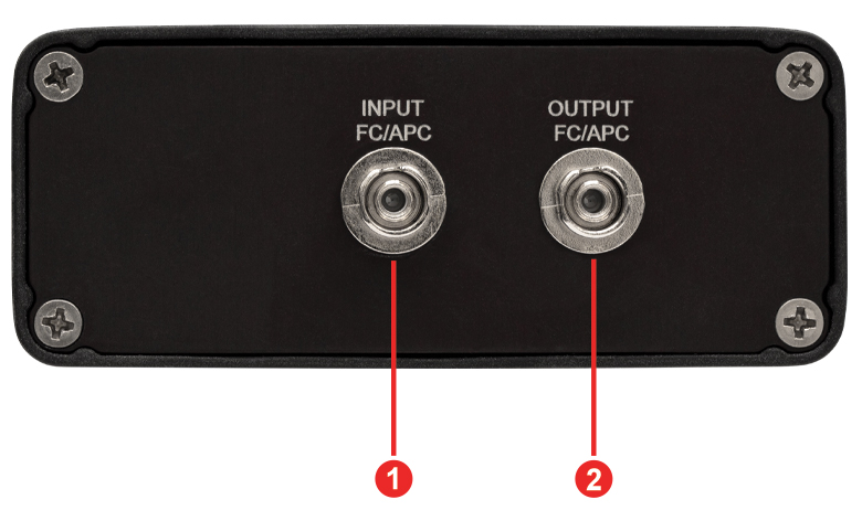
| Callout | Description |
|---|---|
| 1 | Input, FC/APC (2.0 mm Narrow Key) Connector |
| 2 | Output, FC/APC (2.0 mm Narrow Key) Connector |
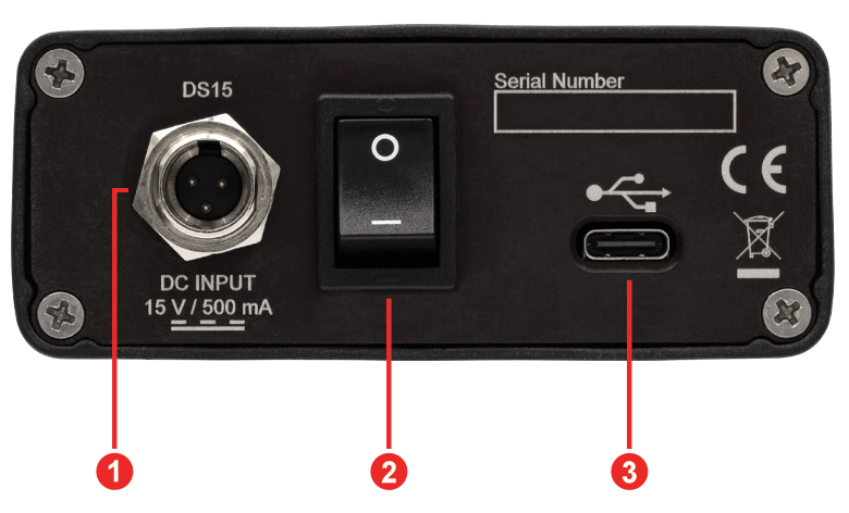
| Callout | Description |
|---|---|
| 1 | 15 VDC Mini-XLR Connector for DS15 Power Supply |
| 2 | Power Switch |
| 3 | USB Type-C Connector for Remote Operation and/or Powering the Device |

Click to Enlarge
The TOF1550 tunable bandpass filter is shipped with the components shown above.
The TOF1550 digital tunable bandpass filter ships with the following components:
| Posted Comments: | |
| No Comments Posted |