
Shack-Hartmann Wavefront Sensors

- CMOS-Based Sensors Capable of Up to 1120 fps
- Sensitivities Up to λ/200
- 300 - 1100 nm or 400 - 900 nm Wavelength Range
- Kits Available with Interchangeable Microlens Arrays (MLAs)
WFS20-5C
High-Speed WFS
with 150 µm Pitch MLA
Application Idea
A WFS20-5C Mounted
on the KM100WFS
Kinematic Mount
WFS31-7AR
General-Purpose WFS
with 150 µm Pitch MLA
WFS40-14AR
Large-Aperture WFS with 300 µm Pitch MLA
OVERVIEW
| Shack-Hartmann Wavefront Sensor Selection Guidea | |||||
|---|---|---|---|---|---|
(Sensor Head) |
Type | Max Speedb | Sensor Size | Wavefront Accuracyb |
Wavefront Sensitivityb |
| WFS31 | General Purpose | Up to 76 fps | 11.25 mm x 7.03 mm | Up to λ/60 | Up to λ/200 |
| WFS40 | Large Aperture | Up to 98 fps | Up to λ/40 | Up to λ/120 | |
| WFS20 | High Speed | ||||
(MLA)c |
Wavelength | Reflectivity | |||
| -5C | Chrome Mask | 300 - 1100 nm | 150 µm | Ø140 µm | <25% |
| -7AR | AR Coating | 400 - 900 nm | 150 µm | Ø146 µm | <1% |
| -14AR | AR Coating | 400 - 900 nm | 300 µm | <1% | |
Features
- Three Compact Sensor Head Options Include:
- General-Purpose Sensor
- Large-Aperture Sensor with 11.26 mm Square Area
- High-Speed Sensor with Frame Rates Up to 1120 fps
- High-Quality Photolithographic Microlens Array (MLA) Included
- Mounted in Exchangeable Magnetic Holder
- Individually Calibrated for the Sensor Head
- Kits Include 2 Microlens Arrays:
- 150 µm Lenslet Pitch with Chrome Mask or AR Coating
- 300 µm Lenslet Pitch with AR Coating
- Real-Time Wavefront and Intensity Distribution Measurements
- Use with CW or Pulsed Light Sources
- USB Connection for PC Operation
- Live Data Readout via TCP/IP
- Flexible Software Options
- GUI Software
- Instrument Driver Package for C Compilers
- LabWindows™/CVI
- LabVIEW®
- DataSocket for Live Data Transfer
- .Net
- Kinematic Mount Designed for Wavefront Sensors Available Separately (See Below)
|
Operating Principle
A Shack-Hartmann sensor consists of a lenslet array and a camera. When a wavefront enters the lenslet array, a spot field is created on the camera. The intensity and location of each spot is analyzed to dynamically measure the wavefronts of laser sources or characterize the wavefront distortion caused by optical components. For more details on the theory of Shack-Hartmann wavefront sensing, see the SH Tutorial tab. |
Thorlabs' Fast Shack-Hartmann Wavefront Sensors provide accurate measurements of the wavefront shape and intensity distribution of incident beams. These wavefront sensors include both a CMOS-based sensor head and a microlens array (MLA). As summarized in the table above, we offer three types of sensor heads: general purpose, large aperture, and high speed. Each type of sensor head is available with three MLA options, which have different lenslet pitches and focal lengths to provide optimal accuracy and wavefront dynamic range for the specific application.
The Item #s for these wavefront sensors have a prefix that refers to the sensor head type (WFS31, WFS40, or WFS20), and a suffix that refers to either the MLA type (-5C, -7A, or -14AR) or the kit type (
Sensor Heads
The general-purpose and large-aperture sensor heads, with Item # Prefixes WFS31 and WFS40 respectively, have a trigger input and USB 3.0 port for connection to a PC. Operation via a USB 2.0 port will result in slower performance. High-speed sensor heads, with Item # Prefix WFS20, include a control box with a trigger input and USB 2.0 port for connection to a PC. The box analyzes the camera image when the sensor is used in high-speed mode and transmits only the spot positions to the PC instead of the entire image. This lowers the volume of data sent over the USB 2.0 connection, allowing the high-speed sensors to achieve measurement speeds of >1000 fps.
Microlens Arrays
MLAs included with our wavefront sensors have a lenslet pitch of either 150 µm or 300 µm, are either chrome masked or AR Coated, and are permanently mounted in a patented (US Patent No. 8,289,504) exchangeable magnetic holder. The magnetic holder positions the microlens array to achieve correct alignment every time it is installed on the sensor head. When a kit or an additional MLA is ordered, Thorlabs includes a removal tool, which makes it easy to switch between MLAs. To purchase an additional MLA or a different combination of MLAs for use with a sensor head, please contact Tech Support. As Thorlabs must calibrate the particular sensor head for use with each specified MLA, upgrading a sensor head for use with additional MLAs requires returning the wavefront sensor to Thorlabs.
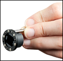
Pickup Tool for Interchanging Microlens Arrays Included with Kits
Software
The included software package offers a user-friendly graphical interface with tools for choosing camera setting, calibration, analysis, and display options. The software also includes drivers for C compilers, LabVIEW®, LabWindows/CVI™, .Net, and DataSocket server support for integration into custom system control and data collection software. For more information on the included software or to download the latest version, see the Software tab above.
Adaptive Optics Kits
In an effort to bring adaptive optics to even more research fields, Thorlabs provides adaptive optics kits. These kits bundle the three primary components for any adaptive optics system: a deformable mirror, a Shack-Hartmann Wavefront Sensor, and real-time control software. We offer Thorlabs' Piezoelectric Deformable Mirrors as well as MEMS-based Deformable Mirrors through our partnership with Boston Micro-Machines. In addition, the kits (shown in the photo to the left) also include a light source, all collimation/imaging optics, and all necessary mounting hardware, except for a breadboard. These kits are specifically designed to provide an affordable, easy-to-use adaptive optics solution that can be integrated into a research system in hours instead of months.
SPECS
| Item # Prefix | WFS31, WFS40, and WFS20 | ||||
|---|---|---|---|---|---|
| Item # Suffix | -5C(/M) | -7AR(/M) | -14AR(/M) | -K1(/M) | -K2(/M) |
| Included Microlens Array(s) | |||||
| 150 µm Lenslet Pitch, Chrome Mask, 300 - 1100 nm |
- | - | - | ||
| 150 µm Lenslet Pitch, ARa Coating, 400 - 900 nm |
- | |
- | - | |
| 300 µm Lenslet Pitch, ARa Coating, 400 - 900 nm |
- | - | |
|
|
Thorlabs' Wavefront Sensors (WFS) combine a CMOS camera and a mounted microlens array (MLA). The performance of the wavefront sensor is primarily dictated by which WFS and MLA you choose. WFS are available with one or two MLAs. New and existing WFS can also be upgraded for use with a maximum of three types of MLA by contacting Tech Support.
The Item #s for these wavefront sensors have a prefix that refers to the sensor head type (WFS31, WFS40, or WFS20), and a suffix that refers to either the MLA type (-5C, -7A, or -14AR) or the kit type (
General-Purpose WFS (Item # Prefix WFS31)
| Software Selectable Camera Resolution Optionsa | ||||||
|---|---|---|---|---|---|---|
| Camera Resolution (Pixels) | Active Area (mm) |
Microlens Spots |
Spot Count |
Frame Rate (fps)c |
||
| Normal Mode |
sub2 Modeb |
Normal Mode |
sub2 Modeb |
|||
| WFS31-5C, WFS31-7AR | ||||||
| 960 x 600 | 73 x 45 | 3285 | 13 | 23 | ||
| 1200 x 1200 | 600 x 600 | 7.03 x 7.03 | 45 x 45 | 2025 | 16 | 27 |
| 1024 x 1024 | 512 x 512 | 6.00 x 6.00 | 39 x 39 | 1521 | 21 | 32 |
| 768 x 768 | 384 x 384 | 4.50 x 4.50 | 29 x 29 | 841 | 30 | 42 |
| 512 x 512 | 256 x 256 | 3.00 x 3.00 | 19 x 19 | 361 | 52 | 59 |
| 368 x 368 | 184 x 184 | 2.16 x 2.16 | 13 x 13 | 169 | 70 | 74 |
| WFS31-14AR | ||||||
| 1920 x 1200 | 960 x 600 | 11.25 x 7.03 | 35 x 21 | 735 | 15 | 25 |
| 1200 x 1200 | 600 x 600 | 7.03 x 7.03 | 21 x 21 | 441 | 18 | 29 |
| 1024 x 1024 | 512 x 512 | 6.00 x 6.00 | 19 x 19 | 361 | 22 | 32 |
| 768 x 768 | 384 x 384 | 4.50 x 4.50 | 13 x 13 | 169 | 34 | 43 |
| 512 x 512 | 256 x 256 | 3.00 x 3.00 | 9 x 9 | 81 | 55 | 61 |
| 368 x 368 | 184 x 184 | 2.16 x 2.16 | 5 x 5 | 25 | 76 | 76 |
| Item #a | ||||
|---|---|---|---|---|
| Microlens Arrays | ||||
| Wavelength Range | ||||
| Microlens Array Aperture Size | 11.5 mm x 7.5 mm | |||
| Mask or Coating | Chrome Mask | Anti-Reflection Coating | ||
| Reflectivity | <25% | <1% | ||
| Lenslet Pitch | 150 µm | 300 µm | ||
| Lenslet Grid Type | Square Grid | |||
| Lens Shapeb | Round, Plano-Convex Spherical | Square, Plano-Convex Parabolic | ||
| Lens Size | Ø140 µm | Ø146 µm | 295 µm x 295 µm | |
| Fill Factor (Approximate)c | 68.4% | 74.4% | 96.7% | |
| Number of Active Lenslets | 73 x 45 (Max), Software-Selectable Options |
35 x 21 (Max), Software-Selectable Options |
||
| Effective Focal Length (Typical, When Mounted in WFS) |
4.1 mm | 5.2 mm | 14.6 mm | |
| Nominal Focal Length | 5.6 mm | 14.2 mm | ||
| Array Size | 12 mm x 12 mm x 1.2 mm | |||
| Substrate Material | Fused Silica (Quartz) | |||
| Camera | ||||
| Sensor Type | CMOS | |||
| Resolution | 1920 x 1200 Pixels (Max), Software-Selectable Options | |||
| Sensor Size, Max | 11.25 mm x 7.03 mm | |||
| Pixel Size | 5.86 µm x 5.86 µm | |||
| Shutter | Globald | |||
| Exposure Range | 31 µs - 2000 ms | |||
| Image Digitization | 8 Bit | |||
| Wavefront Measurement | ||||
| Accuracy (at 633 nm)e | λ/25 rms | λ/40 rms | λ/60 rms | |
| Sensitivity (at 633 nm)f | λ/80 rms | λ/120 rms | λ/200 rms | |
| Dynamic Range (at 633 nm)g | >500λ | >500λ | >250λ | |
| Local Curvatureh | >7.4 mm | >10.0 mm | >40.0 mm | |
| General Specifications | |||
|---|---|---|---|
| External Trigger Input Specifications | |||
| Trigger Slope | Software Selectable: Low-High or High-Low |
||
| Safe Static Input Voltage Range | 0 to 30 VDC | ||
| Low Level | 0.0 V to 2.0 V | ||
| High Level | 5.0 V to 24 V | ||
| Input Current (Max) | 10 mA | ||
| Pulse Width (Min) | 100 µs | ||
| Slew Rate (Min) | 35 V/ms | ||
| Housing Dimensions and Threads | |||
| Optical Input Thread | Internal C-Mount | ||
| Dimensions (H x W x D) | 35.4 mm x 29.8 mm x 47.9 mm (1.39" x 1.17" x 1.89") |
||
| External Power Supply | Max 2.8 W, via USB 3.0a | ||
| Operating Temperature | 5 to 35 °C (Non-Condensing) | ||
| Storage Temperature | -20 to 60 °C | ||
| Warm-Up Time for Rated Accuracy | 15 Minutes | ||
| Post Mountingb | One 8-32 (M4) Tap, One 1/4"-20 (M6) Tap |
||
| Cage Mounting | - | ||
| Included Thread Adapter | SM1A9: External C-Mount to Internal SM1 (1.035"-40) |
||
All technical data are valid at 23 ± 5° C and 45 ± 15% relative humidity (non-condensing).
Large-Aperture WFS (Item # Prefix WFS40)
| Software Selectable Camera Resolution Optionsa | ||||||
|---|---|---|---|---|---|---|
| Camera Resolution (Pixels) | Active Area (mm) |
Microlens Spots |
Spot Count |
Frame Rate (fps)c |
||
| Normal Mode |
sub2 Modeb | Normal Mode |
sub2 Modeb | |||
| WFS40-5C, WFS40-7AR | ||||||
| 73 x 73 | 5329 | 8 | 19 | |||
| 1536 x 1536 | 768 x 768 | 8.45 x 8.45 | 55 x 55 | 3025 | 13 | 30 |
| 1024 x 1024 | 512 x 512 | 5.63 x 5.63 | 35 x 35 | 1225 | 26 | 55 |
| 768 x 768 | 384 x 384 | 4.22 x 4.22 | 27 x 27 | 729 | 41 | 82 |
| 512 x 512 | 256 x 256 | 2.82 x 2.82 | 17 x 17 | 289 | 70 | 98 |
| 360 x 360 | 180 x 180 | 1.98 x 1.98 | 11 x 11 | 121 | 98 | 98 |
| WFS40-14AR | ||||||
| 2048 x 2048 | 1024 x 1024 | 11.26 x 11.26 | 35 x 35 | 1225 | 10 | 28 |
| 1536 x 1536 | 768 x 768 | 8.45 x 8.45 | 27 x 27 | 729 | 15 | 41 |
| 1024 x 1024 | 512 x 512 | 5.63 x 5.63 | 17 x 17 | 289 | 29 | 70 |
| 768 x 768 | 384 x 384 | 4.22 x 4.22 | 13 x 13 | 169 | 44 | 95 |
| 512 x 512 | 256 x 256 | 2.82 x 2.82 | 7 x 7 | 49 | 76 | 98 |
| 360 x 360 | 180 x 180 | 1.98 x 1.98 | 5 x 5 | 25 | 98 | 98 |
| Item #a | ||||
|---|---|---|---|---|
| Microlens Arrays | ||||
| Wavelength Range | ||||
| Microlens Array Aperture Size | 11.5 mm x 11.5 mm | |||
| Mask or Coating | Chrome Mask | Anti-Reflection Coating | ||
| Reflectivity | <25% | <1% | ||
| Lenslet Pitch | 150 µm | 300 µm | ||
| Lenslet Grid Type | Square Grid | |||
| Lens Shapeb | Round, Plano-Convex Spherical | Square, Plano-Convex Parabolic | ||
| Lens Size | Ø140 µm | Ø146 µm | 295 µm x 295 µm | |
| Fill Factor (Approximate)c | 68.4% | 74.4% | 96.7% | |
| Number of Active Lenslets | 73 x 73 (Max), Software-Selectable Options |
35 x 35 (Max), Software-Selectable Options |
||
| Effective Focal Length (Typical, When Mounted in WFS) |
4.1 mm | 5.2 mm | 14.6 mm | |
| Nominal Focal Length | 5.6 mm | 14.2 mm | ||
| Array Size | 12 mm x 12 mm x 1.2 mm | |||
| Substrate Material | Fused Silica (Quartz) | |||
| Camera | ||||
| Sensor Type | CMOS | |||
| Resolution | 2048 x 2048 Pixels (Max), Software-Selectable Options | |||
| Sensor Size, Max | 11.26 mm x 11.26 mm | |||
| Pixel Size | 5.5 µm x 5.5 µm | |||
| Shutter | Globald | |||
| Exposure Range | 77 µs - 499 ms | |||
| Image Digitization | 8 Bit | |||
| Wavefront Measurement | ||||
| Accuracy (at 633 nm)e | λ/25 rms | λ/30 rms | λ/40 rms | |
| Sensitivity (at 633 nm)f | λ/80 rms | λ/100 rms | λ/120 rms | |
| Dynamic Range (at 633 nm)g | >500λ | >500λ | >250λ | |
| Local Curvatureh | >7.4 mm | >10.0 mm | >40.0 mm | |
| General Specifications | |||
|---|---|---|---|
| External Trigger Input Specifications | |||
| Trigger Slope | Software Selectable: Low-High or High-Low |
||
| Safe Static Input Voltage Range | 0 to 30 VDC | ||
| Low Level | 0.0 V to 2.0 V | ||
| High Level | 5.0 V to 24 V | ||
| Input Current (Max) | 10 mA | ||
| Pulse Width (Min) | 100 µs | ||
| Slew Rate (Min) | 35 V/ms | ||
| Housing Dimensions and Threads | |||
| Optical Input Thread | Internal C-Mount | ||
| Dimensions (H x W x D) | 35.4 mm x 29.8 mm x 48.3 mm (1.39" x 1.17" x 1.90") |
||
| External Power Supply | Max 2.9 W, via USB 3.0a | ||
| Operating Temperature | 5 to 35 °C (Non-Condensing) | ||
| Storage Temperature | -20 to 60 °C | ||
| Warm-Up Time for Rated Accuracy | 15 Minutes | ||
| Post Mountingb | One 8-32 (M4) Tap, One 1/4"-20 (M6) Tap |
||
| Cage Mounting | - | ||
| Included Thread Adapter | SM1A9: External C-Mount to Internal SM1 (1.035"-40) |
||
All technical data are valid at 23 ± 5° C and 45 ± 15% relative humidity (non-condensing).
High-Speed WFS (Item # Prefix WFS20)
| Software Selectable Camera Resolution Optionsa | ||||||
|---|---|---|---|---|---|---|
| Camera Resolution (Pixels) |
Active Area (mm) |
Microlens Spots |
Spot Count |
Frame Rate (fps)b | ||
| Normal Mode |
2X Binningc |
Mode |
||||
| WFS20-5C and WFS20-7AR | ||||||
| 1645 | 23 | 58 | 150 | |||
| 1080 x 1080 | 5.40 x 5.40 | 35 x 35 | 1225 | 29 | 69 | 166 |
| 768 x 768 | 3.84 x 3.84 | 23 x 23 | 529 | 50 | 144 | 350 |
| 512 x 512 | 2.56 x 2.56 | 15 x 15 | 225 | 79 | 320 | 710 |
| 360 x 360 | 1.80 x 1.80 | 11 x 11 | 121 | 116 | 630 | 880 |
| WFS20-14AR | ||||||
| 1440 x 1080 | 7.20 x 5.40 | 23 x 17 | 391 | 28 | 92 | 183 |
| 1080 x 1080 | 5.40 x 5.40 | 17 x 17 | 289 | 33 | 123 | 226 |
| 768 x 768 | 3.84 x 3.84 | 11 x 11 | 121 | 50 | 258 | 394 |
| 512 x 512 | 2.56 x 2.56 | 7 x 7 | 49 | 79 | 450 | 725 |
| 360 x 360 | 1.80 x 1.80 | 5 x 5 | 25 | 116 | 648 | 1120 |
| Item #a | ||||
|---|---|---|---|---|
| Microlens Arrays | ||||
| Wavelength Range | ||||
| Microlens Array Aperture Size | Ø9 mm | |||
| Mask or Coating | Chrome Mask | Anti-Reflection Coating | ||
| Reflectivity | <25% | <1% | ||
| Lenslet Pitch | 150 µm | 300 µm | ||
| Lenslet Grid Type | Square Grid | |||
| Lens Shapeb | Round, Plano-Convex Spherical | Square, Plano-Convex Parabolic | ||
| Lens Size | Ø140 µm | Ø146 µm | 295 µm x 295 µm | |
| Fill Factor (Approximate)c | 68.4% | 74.4% | 96.7% | |
| Number of Active Lenslets | 47 x 35 (Max), Software-Selectable Options |
23 x 17 (Max), Software-Selectable Options |
||
| Effective Focal Length (Typical, When Mounted in WFS) |
4.1 mm | 5.2 mm | 14.6 mm | |
| Nominal Focal Length | 5.6 mm | 14.2 mm | ||
| Array Size | 10 mm x 10 mm x 1.2 mm | |||
| Substrate Material | Fused Silica (Quartz) | |||
| Camera | ||||
| Sensor Type | CMOS | |||
| Resolution | 1440 x 1080 Pixels (Max), Software-Selectable Options | |||
| Sensor Size, Max | 7.20 mm x 5.40 mm | |||
| Pixel Size | 5.0 µm x 5.0 µm | |||
| Shutter | Globald | |||
| Exposure Range | 4 µs - 83.3 ms | |||
| Image Digitization | 8 Bit | |||
| Wavefront Measurement | ||||
| Accuracy (at 633 nm)e | λ/30 rms | λ/60 rms | ||
| Sensitivity (at 633 nm)f | λ/100 rms | λ/200 rms | ||
| Dynamic Range (at 633 nm)g | >100λ | >50λ | ||
| Slope (Max)h | ±1.0° | ±0.8° | ±0.5° | |
| Local Curvaturei | >7.4 mm | >10.0 mm | >40.0 mm | |
| General Specifications | |||
|---|---|---|---|
| External Trigger Input Specifications | |||
| Trigger Slope | Software Selectable: Low-High or High-Low |
||
| Safe Input Voltage Range | -0.5 to 6.5 V | ||
| Low Level (Max) | 1.5 V | ||
| High Level (Min) | 3.5 V | ||
| Input Impedance | >100 kΩ | ||
| Pulse Width (Min) | 10 µs | ||
| Slew Rate (Min) | 5 V/ns | ||
| Housing Dimensions and Threads | |||
| Optical Input Thread | Internal C-Mount | ||
| Camera Head Dimensions (H x W x D) |
46.0 mm x 56.0 mm x 33.1 mm (1.81" x 2.20" x 1.30") |
||
| FPGA Box Dimensions (H x W x D) |
27.5 mm x 57.0 mm x 98.4 mm (1.08" x 2.24" x 3.87") |
||
| External Power Supply | 12 V, 1.5 A | ||
| Operating Temperature | 5 to 35 °C (Non-Condensing) | ||
| Storage Temperature | -20 to 60 °C | ||
| Warm-Up Time for Rated Accuracy | 15 Minutes | ||
| Post Mounting | Three 8-32 (M4) Taps | ||
| Cage Mounting | Four 4-40 Taps for 30 mm Cage Systems | ||
| Included Thread Adapter | SM1A9: External C-Mount to Internal SM1 (1.035"-40) |
||
All technical data are valid at 23 ± 5° C and 45 ± 15% relative humidity (non-condensing).
SH TUTORIAL
Shack-Hartmann Wavefront Sensors
Wavefront sensors allow a user to analyze the shape of an incident beam's wavefront in order to identify or correct aberations caused by light traveling through individual optics or optical assemblies. Shack-Hartmann wavefront sensors achieve this by dividing the beam into an array of discrete intensity points using a microlens array. These data are used to reconstruct and analyze the shape of the wavefront using Zernike polynomials. In addition to analyzing classical optics phenomena, they are increasingly used in applications where real-time monitoring of the wavefront is used to control adaptive optics with the intent of removing the wavefront distortion before creating an image.
Spot Field Overview
To measure the wavefront of a beam, the light is aligned so that it is normally incident on the microlens array at the front of the wavefront sensor. Each lenslet collects the light filling its aperture and forms a single focal spot on the CMOS camera sensor, which is located at the focal plane of the microlens array. If the wavefront is planar, all focal spots are centered directly behind each respective lens, coincident with the optical axis of each. The result is a regularly spaced grid of spots on the camera sensor, as illustrated in Figure 1. These spot locations are called reference spot positions, and they compose the reference spot field.

Click to Enlarge
Figure 2: The displacements of the focal spots from their respective reference positions are used to calculate the shape of the incident wavefront.

Click to Enlarge
Figure 1: Focal spots are centered directly behind each lens when the incident wavefront is planar. This is the reference spot field.
When the wavefront is distorted, focal spots will be displaced from their reference positions on the camera sensor. Distorted wavefronts may also result in spot fields that include missing spots, as illustrated in Figure 2. By comparing the locations of the spots in the measured spot field with those in the reference spot field, the shape of the wavefront can be calculated.
Wavefront Distortion and Spot Displacement
The shape of the beam's wavefront may be complex when the entire cross section is considered; however, across the small portion of the beam collected by a single lenslet, the wavefront is approximately planar. The region surrounding a single lenslet of the microlens array is shown in Figure 3, using parallel lines to indicate both wavefronts are planar over these limited dimensions. The difference between the wavefronts is represented by their respective orientations to the optical axis of the lens.
The propagation angle of this portion of the beam is determined by the local shape of the distorted wavefront. If this region of the wavefront is not distorted, the collected light propagates along each lens' optical axis, and the focal spot is centered directly behind the lens (green circle). If instead this portion of the wavefront is distorted, its propagation angle, α, with respect to the lens' optical axis, results in a focal spot (red circle) displaced from the reference spot.
The propagation angle for this portion of the beam, and therefore the local shape of the wavefront, can be found using the focal length of the lens, fML, and the relative position of the focal spot with respect to the reference spot (δx, δy). The shape of the wavefront across the entire cross section of the beam is computed through the 2-dimensional integration of all spot displacements. Thorlabs' wavefront sensor software performs these calculations and defines the center of the spot field as the origin for the integration.

Click to Enlarge
Figure 3: Above is a diagram showing a single lenslet. Waves with planar wavefronts (green parallel lines) are normally incident on the lens and focus to the reference spot position (green circle). Distorted wavefronts (red parallel lines) are not normally incident and focus to a location (red circle) displaced from the reference spot. The displacement angle, α, can be calculated from the geometry.
Calculating Sensitivity and Dynamic Range
Measurement Sensitivity
Sensitivity (i.e. the minimum displacement angle, αmin) is a function of the minimum detectable spot displacement (δymin), as described by the equation:
αmin = δymin / fML
where fML is the focal length of the microlens.
Dynamic Range
Dynamic range (i.e. the maximum displacement angle, αmax) is a measure of the maximum extent of phase that can be measured:
αmax = δymax / fML = (D / 2) / fML
where D is the diameter of the microlens. Both of these equations were derived using the small angle approximation. αmin is the minimum detectable wavefront slope that can be measured by the wavefront sensor. The minimum detectable spot displacement δymin depends on the pixel size of the detector, the accuracy of the centroid algorithm, and the signal to noise ratio of the sensor. αmax is the maximum wavefront slope that can be measured by the wavefront sensor and corresponds to a spot displacement of δymax, which is equal to the lenslet radius.
A conventional algorithm will fail to determine the correct centroid of a spot if it partially overlaps another spot or if the focal spot of a lenslet falls outside of the area of the sensor assigned to detect it (spot crossover). Special algorithms can be implemented to overcome these problems but limit the dynamic range of the sensor. The dynamic range of a system can be increased by using a lenslet with either a larger diameter or a shorter focal length. Increasing the dynamic range by increasing the lenslet diameter decreases the number of Zernike coefficients available to represent the wavefront. Conversely, increasing the dynamic range by shortening the focal length decreases the sensor's sensitivity. Ideally, a lenslet with the longest focal length that meets both the dynamic range and measurement sensitivity requirements should be used.
Factors Affecting Shack-Hartmann Measurement Accuracy
A Shack-Hartmann wavefront sensor's measurement accuracy (i.e., the minimum wavefront slope that can be measured reliably) depends on its ability to precisely measure the displacement of a focused spot with respect to a reference position. Several factors influence the measurement accuracy, including the lens pitch of the microlens array, the active area of the sensor (pupil diameter or camera resolution selection), the beam size, and the operating mode. Finer details of the wavefront can be reconstructed when there are greater numbers of focal spots to analyze. Eliminating the effects of ambient light, through a combination of software settings and experimental techniques to reduce stray light also increases measurement accuracy. Factors impacting accuracy are elaborated on below; further information can be found in the product manual.
Number of Focal Spots
The number of focal spots is determined by the pitch of the microlens array, the active area of the sensor (pupil diameter or camera resolution), and the beam size. Microlens arrays with a smaller pitch provide a greater density of measurement points for a given beam, providing higher spatial resolution, assuming all measurements are within the dynamic range of the sensor. The benefit of having larger numbers of focal spots in the spot field is particularly apparent when Zernike polynomials are used to analyze the wavefront aberrations, as the number of Zernike modes cannot exceed the number of detected focal spots. Arrays with a larger pitch provide higher wavefront accuracy.
The active area of the camera sensor is set by the user in the software. Choosing a smaller active area increases the frame rate, but information about the wavefront is lost when the active area is smaller than the beam diameter. If the beam diameter itself is small, then there will be a small number of focal spots, regardless of the active area of the camera sensor. Ideally, the beam should slightly overfill the microlens array to remove edge effects and allow any user selected area to be highlighting active pixels.
Operating Mode
Shack-Hartmann sensors can collect and average data in different ways. For our wavefront sensors, there are a total of 4 operating modes supported to varying degrees depending on the sensor type. It is important to understand that by collecting data faster, for example, may require data to be averaged. Depending on how the data is averaged, accuracy may drop. The operating modes available for our sensors are expanded on in further detail in the Selection Guide tab.
Image Averaging and Background Level Settings
Measurement accuracy can be increased when the average of several images, rather than a single image, is used for calculations. The wavefront sensor software includes the option to calculate normal or rolling averages. Both options compute pixel-by-pixel averages of the user-specified number of images, N. Normal averaging acquires unique sets of N images for each measurement and results in a decreased frame rate. For rolling averages, a set of N images is averaged for the first measurement, but, the next measurement will remove the first image of the set and add in the next image taken N+1. The frame rate is higher when a rolling average is used, where every frame is averaged instead of every set of frames increases. This also provides a more up-to-date status of the wavefront.
In addition to reducing stray light using lens tubes and other experimental techniques, we recommend adjusting the Noise Cut Level and Black Level settings as appropriate for the application. The software provides an intuitive and simple tool to assist with this. The Black Level setting adjusts the brightness level offset applied to all pixels. The Noise Cut Level defines a minimum brightness threshold the software uses when performing calculations, and it is used to prevent errors in focal spot calculations resulting from the effects of ambient light and/or noise. Intensity measurements below the Noise Cut Level are set to zero. The recommended Noise Cut Level setting is 'Auto,' as this setting dynamically adapts to changing light levels.
SELECTION GUIDE
Shack-Hartmann Wavefront Sensors include a sensor head and a microlens array (MLA), and the performance of the sensor depends on both. In the following, the Item # prefix of each wavefront sensor (WFS20, WFS31, or WFS40) is used to refer to the respective sensor head, while the Item # Suffixes -5C, -7AR, and -14AR are used to refer to the different MLA options. Please note that while Thorlabs offers a selection of wavefront sensors with one or two MLAs, available below, any of these sensor heads can be factory-calibrated for use with a maximum of three types of MLA by contacting Tech Support. Thorlabs also offers an upgrade service for existing WFS by contacting Tech Support.
Click to Enlarge
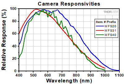
Figure 1: Normalized Responsivities for the Camera Sensors in Each Wavefront Sensor Head
Sensor Head
Each sensor head (Item # Prefix: WFS31, WFS40, or WFS20) is based on a different CMOS camera. While the cameras provide different measurement performance, each wavefront sensor is operated using the same software application.
Camera Responsivity
The responsivities of the three cameras, which are similar, are plotted in Figure 1. The WFS20 sensor heads have higher relative responsivities at longer wavelengths and a flatter region of peak responsivity. The WFS31 sensor has higher relative responsivities at lower wavelengths.
Free Aperture and Camera Resolution
The maximum free aperture and camera resolution are coupled for these wavefront sensors. The WFS20 and WFS31 offer rectangular apertures, with the smaller dimension limiting the maximum diameter of incident circular beams. The WFS40 is approximately 30% larger along its sides compared to the WFS20 and WFS31; it provides a square aperture that accepts an input beam of up to Ø11 mm.
Operating Modes and Measurement Speed
Wavefront sensors that include the WFS31 or WFS40 sensor heads can operate in Normal Mode or the sub2 (subsampling) Mode. There is no High-Speed Mode option offered for these sensor heads. The entire spot field image acquired by the camera is transmitted to the PC in both operating modes. When operating in sub2 Mode, the frame rate is increased by using a single pixel from each 2 x 2 set of pixels for the calculation of focal spot centroids. The drawback is wavefront measurements with reduced accuracy.
The camera included with the WFS20 operates at faster speeds than the cameras that are included in the WFS31 and WFS40. Thorlabs takes advantage of the WFS20's faster camera by offering three operating modes: Normal Mode, 2 x 2 Binning Mode (Bin 2), and High-Speed Mode.
In the WFS20's normal mode, the frame rates are limited by the time needed to transmit the full spot field image from the camera to the PC, as well as by the time required to perform the calculations.
The faster 2 x 2 Binning mode improves the WFS20's frame rates by reducing calculation time. Instead of using the data from every pixel in the active area to calculate the focal spot centroids, the average value for the four pixels in every 2 x 2 set is used. The drawback is reduced spatial wavefront resolution.
In the WFS20's High-Speed Mode, the focal spot centroids are calculated by the fast field-programmable gate array (FPGA) built into the WFS20's Control Box. Not only can the FPGA calculate the spot centroids more quickly than the PC, but only the spot centroid data points are transmitted to the PC. This greatly decreases the amount of data that needs to be transferred to the PC, providing the fastest measurement speeds. A drawback is that it is not possible to view or manipulate the camera image in the GUI during operation in High-Speed Mode, which makes it harder to detect certain errors, such as those caused by camera saturation.
Physical Dimensions and Mounting Options
WFS20 sensor heads include both a sensor head and a control box, while the WFS31 and WFS40 options have only a sensor head. In addition, the dimensions of the WFS20 sensor head (46.0 mm x 56 mm x 33.1 mm) are larger than the common dimensions of the WFS31 and WFS40 sensor heads (35.4 mm x 29.8 mm x 42.6 mm).
All include an SM1A9 adapter for converting the external C-Mount to Internal SM1 (1.035"-40) threads, so that lens tubes can be used to reduce scattered light and neutral density filters can be used to prevent device saturation. The WFS20 also has three 8-32 (M4) taps on the bottom of the housing for mounting on Ø1/2" posts and four 4-40 taps on the front face for compatibility with Thorlabs' 30 mm Cage Systems. The WFS31 and WFS40 include a bottom-mounted adapter plate with an 8-32 (M4) and a 1/4"-20 (M6) tap for mounting the sensor head on Ø1/2" posts.
| Microlens Array Key Specificationsa | |||||||||
|---|---|---|---|---|---|---|---|---|---|
| Item # Suffix | Mask or Coating | Wavelength | Lenslet Pitch | Lenslet Size | Reflectivity | High Spot Contrast |
High Wavefront Accuracy |
High Spatial Resolution |
Low Back Reflection |
| -5C | <25% | - | - | ||||||
| -7AR | AR Coating | 400 - 900 nm | 150 µm | Ø146 µm | <1% | - | - | ||
| -14AR | 400 - 900 nm | 300 µm | 295 µm x 295 µm | <1% | - | - | |||
Microlens Arrays
The choice of microlens array affects frame rates and the quality of the wavefront measurement.
Chrome Mask vs. Anti-Reflection (AR) Coating
The chrome mask is a grid that frames each microlens. The mask blocks light from being transmitted unless it passes through a microlens, which increases image contrast. However, the reflections from MLA back to the source are high. The specified wavelength range is equal to that of the quartz substrate.
The AR Coating reduces the back reflections from the MLA within the specified wavelength range. The specified reflectivity of the AR coated MLA is valid only within the stated wavelength range.
Outside of this wavelength range, the reflectivity may increase significantly. Note that the total reflectivity of the instrument may be higher due to reflections from the CMOS camera chip and its window.
Lens Pitch
An MLAs lens pitch defines the distance measured from the center of a lens to the center of the lens next to it. So, MLAs with a 150 µm lens pitch offer a larger number of spots and thus a higher spatial resolution of the wavefront, and a wider wavefront dynamic range because of their shorter focal length. The MLA with a 300 µm supports higher wavefront accuracy and sensitivity at the expense of dynamic range and spatial resolution.
Frame Rates
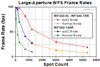
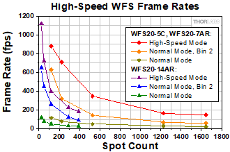
Frame rates depend on the sensor head, operation mode, and microlens array and scale with the number of focal spots, as is discussed in the preceding. The frame rates for each combination of sensor head, microlens array, operation mode, and spot count are plotted in Figures 2 through 4.

Click to Enlarge
Figure 2: Frame Rates of Wavefront Sensors with Item # Prefix WFS31
Click to Enlarge
Figure 3: Frame Rates of Wavefront Sensors with Item # Prefix WFS40
Click to Enlarge
Figure 4: Frame Rates of Wavefront Sensors with Item # Prefix WFS20
SHIPPING LIST&NBSP;
General-Purpose Wavefront Sensor

Click to Enlarge
WFS31-5C Package Contents
- General-Purpose Sensor Head
- Item # Specific MLA Installed on Sensor Head
- WFS31-5C(/M): MLA with Chrome Mask and 150 µm Lenslet Pitch
- WFS31-7AR(/M): MLA with Anti-Reflection Coating and 150 µm Lenslet Pitch
- WFS31-14AR(/M): MLA with Anti-Reflection Coating and 300 µm Lenslet Pitch
- SM1A9 Adapter
- Dust Cap
- USB 3.0 Type-A to Mini-B Cable, 3 m
- Quick-Start Guide (Not Shown)
General-Purpose Wavefront Sensor Kit

Click to Enlarge
WFS31-K2 Package Contents
- General-Purpose Sensor Head
- Item # Specific MLA Installed on Sensor Head
- WFS31-K1(/M): MLA with Chrome Mask and 150 µm Lenslet Pitch
- WFS31-K2(/M): MLA with Anti-Reflection Coating and 150 µm Lenslet Pitch
- Additional MLA, with Anti-Reflection Coating and 300 µm Lenslet Pitch, Packaged Separately
- SM1A9 Adapter
- Dust Cap
- Tool to Facilitate MLA Exchange
- USB 3.0 Type-A to Mini-B Cable, 3 m
- Quick-Start Guide (Not Shown)
Large-Aperture Wavefront Sensor

Click to Enlarge
WFS40-14AR Package Contents
- Large-Aperture Sensor Head
- Item # Specific MLA Installed on Sensor Head
- WFS40-5C(/M): MLA with Chrome Mask and 150 µm Lenslet Pitch
- WFS40-7AR(/M): MLA with Anti-Reflection Coating and 150 µm Lenslet Pitch
- WFS40-14AR(/M): MLA with Anti-Reflection Coating and 300 µm Lenslet Pitch
- SM1A9 Adapter
- Dust Cap
- USB 3.0 Type-A to Mini-B Cable, 3 m
- Quick-Start Guide (Not Shown)
Large-Aperture Wavefront Sensor Kit

Click to Enlarge
WFS40-K1 Package Contents
- Large-Area Sensor Head
- Item # Specific MLA Installed on Sensor Head
- WFS40-K1(/M): MLA with Chrome Mask and 150 µm Lenslet Pitch
- WFS40-K2(/M): MLA with Anti-Reflection Coating and 150 µm Lenslet Pitch
- SM1A9 Adapter
- Dust Cap
- Tool to Facilitate MLA Exchange
- Additional MLA, with Anti-Reflection Coating and 300 µm Lenslet Pitch, Packaged Separately
- USB 3.0 Type-A to Mini-B Cable, 3 m
- Quick-Start Guide (Not Shown)
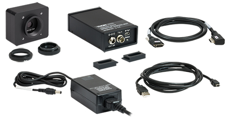
High-Speed Wavefront Sensor
Click to Enlarge
WFS20-7AR Package Contents
- High-Speed Sensor Head
- Item # Specific MLA Installed on Sensor Head
- WFS20-5C(/M): MLA with Chrome Mask and 150 µm Lenslet Pitch
- WFS20-7AR(/M): MLA with Anti-Reflection Coating and 150 µm Lenslet Pitch
- WFS20-14AR(/M): MLA with Anti-Reflection Coating and 300 µm Lenslet Pitch
- Control Box
- PoCL Cable to Connect Sensor Head and Control Box
- SM1A9 Adapter
- Dust Cap
- Two Clamps to Secure Control Box
- Power Supply with Location-Specific Plug, 12 V and 1.5 A
- USB 2.0 Type-A to Mini-B Cable, 2 m
- Quick-Start Guide (Not Shown)
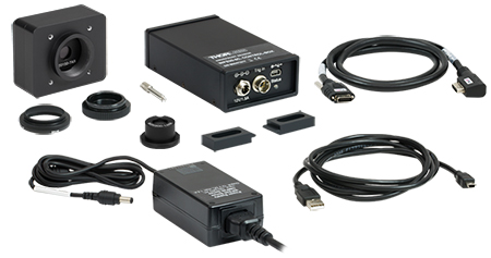
High-Speed Wavefront Sensor Kit
Click to Enlarge
WFS20-K1 Package Contents
- High-Speed Sensor Head
- Item # Specific MLA Installed on Sensor Head
- WFS20-K1(/M): MLA with Chrome Mask and 150 µm Lenslet Pitch
- WFS20-K2(/M): MLA with Anti-Reflection Coating and 150 µm Lenslet Pitch
- Additional MLA, with Anti-Reflection Coating and 300 µm Lenslet Pitch, Packaged Separately
- Control Box
- PoCL Cable to Connect Sensor Head and Control Box
- SM1A9 Adapter
- Dust Cap
- Tool to Facilitate MLA Exchange
- Two Clamps to Secure Control Box
- Power Supply with Location-Specific Plug, 12 V and 1.5 A
- USB 2.0 Type-A to Mini-B Cable, 2 m
- Quick-Start Guide (Not Shown)
SOFTWARE
Software Download
Click on the Software button to the right for the latest version of Thorlabs' Shack-Hartmann Wavefront Sensor Software Package. The download includes the software package with a graphical user interface for operating the WFS in standard applications and support for developers who want to extend or adapt the functionality of the device to their special requirements.
System Requirements:
- Windows® 10 (32 or 64 Bit) or 11
- USB Interface
- WFS20 Series: USB 2.0 or 3.0 Port
- WFS31 or WFS40 Series: USB 3.0 Port
- Graphic Card: 256 MB Memory (Min, Shared)
- Graphic Resolution: 1024 x 768 Min, 1280 x 1024 Recommended
- Free Storage Space: 500 MB (Min)
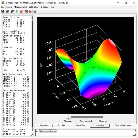
GUI Display of Measured Wavefront
Software and Graphical User Interface
Display/Output Options
For screen images of the GUI display options, please click on the links:
- Raw Spotfield Image
- Zernike Coefficients
- Measured and Reconstructed 3D Wavefront
- Irradiance Distribution
- Lineview Intensity of Pixel Column
- Tabulated Output
- Flexible Export Option: Text or Excel File
- Live Data Readout via TCP/IP to a DataSocket Server
Calculated Parameters
- Beam Centroid and Diameter
- Modal and Zonal Reconstructed Wavefront
- Max Variance of Wavefront, Peak-to-Valley (PV), and RMS of Wavefront
- Zernike Representations of Tilt, Defocus, Astigmatism,
Coma, Spherical, and Higher Order Aberrations - Fourier and Optometric Parameters
Included Drivers
The software includes a driver package for constructing custom applications with the following software packages:
- C Compilers
- LabWindows™/CVI
- LabVIEW®
- .Net
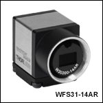
General-Purpose Wavefront Sensors

Click to Enlarge
Frame rate and resolution depend on the MLA, software-selectable active area, and operation mode.
- Rectangular 11.25 mm x 7.03 mm Max Aperture
- 1920 x 1200 Pixel Max Camera Resolution
- One Mounted Microlens Array Included with Each WFS
- Chrome Mask or AR Coating
- 150 µm Pitch Arrays Have 73 x 45 Active Lenslets (Max)
- 300 µm Pitch Array Has 35 x 21 Active Lenslets (Max)
- User-Selectable Software Settings Control Frame Rate and Resolution
- Pupil Size Adjustment
- Operation in Normal or Faster Subsampling (sub2) Mode
- Software Controlled via Thorlabs' or User-Developed Application
Each of these Wavefront Sensors (WFS) is calibrated for use with the included mounted microlens array (MLA). A USB 3.0 interface to a PC running the software application is required to provide the specified performance (see the Specs tab); however, these instruments can be operated with reduced performance via a USB 2.0 interface. Each WFS includes a bottom-mounted adapter plate with an 8-32 (M4) and a 1/4"-20 (M6) tap for mounting the sensor head on Ø1/2" posts.
Kits, available below, include two MLAs calibrated for the sensor head. If a MLA has not been factory-calibrated for use with a particular sensor head, it should not be used. Contact Tech Support to upgrade a WFS for use with additional MLAs.
| General Purpose Wavefront Sensorsa | |||
|---|---|---|---|
| Item # | |||
| Wavelength Range | 300 - 1100 nm | 400 - 900 nm | |
| Effective Focal Length | 4.1 mm | 5.2 mm | 14.6 mm |
| Lenslet Array Coating | Chrome Mask | AR Coated | |
| Lenslet Pitch | 150 µm | 300 µm | |
| Wavefront Accuracy (at 633 nm)b | λ/25 rms | λ/40 rms | λ/60 rms |
| Wavefront Sensitivity (at 633 nm)c | λ/80 rms | λ/120 rms | λ/200 rms |
| Frame Rate | 13 - 74 fps | 15 - 76 fps | |
| Camera Resolution | 1920 x 1200 Pixels Max, Software Selectable | ||
| High-Speed Control Box with PoCL and Table Clamps |
- | ||
| Included Cable | USB 3.0 Type-A to Mini-B Cable, 3 m | ||
Part Number | Description | Price | Availability |
|---|---|---|---|
WFS31-5C/M | Shack-Hartmann WFS, 11.25 mm x 7.03 mm Aperture, 150 µm Pitch, Chrome-Masked MLA, 300 - 1100 nm, Metric Taps | $4,381.23 | 3-5 Days |
WFS31-7AR/M | Shack-Hartmann WFS, 11.25 mm x 7.03 mm Aperture, 150 µm Pitch, AR Coated MLA, 400 - 900 nm, Metric Taps | $4,381.23 | 3-5 Days |
WFS31-14AR/M | Shack-Hartmann WFS, 11.25 mm x 7.03 mm Aperture, 300 µm Pitch, AR Coated MLA, 400 - 900 nm, Metric Taps | $4,381.23 | 3-5 Days |
WFS31-5C | Shack-Hartmann WFS, 11.25 mm x 7.03 mm Aperture, 150 µm Pitch, Chrome-Masked MLA, 300 - 1100 nm, Imperial Taps | $4,381.23 | 3-5 Days |
WFS31-7AR | Shack-Hartmann WFS, 11.25 mm x 7.03 mm Aperture, 150 µm Pitch, AR Coated MLA, 400 - 900 nm, Imperial Taps | $4,381.23 | 3-5 Days |
WFS31-14AR | Shack-Hartmann WFS, 11.25 mm x 7.03 mm Aperture, 300 µm Pitch, AR Coated MLA, 400 - 900 nm, Imperial Taps | $4,381.23 | 3-5 Days |
General-Purpose Wavefront Sensor Kits
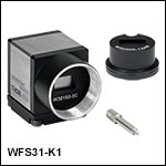
- Includes General-Purpose Wavefront Sensor and an Additional 300 µm Pitch AR-Coated MLA
- MLAs Factory Calibrated for Use with the Included Hardware
- WFS31-K1(/M) Can Be Configured as:
- WFS31-5C(/M) by Installing the MLA with 150 µm Pitch and Chrome Mask
- WFS31-14AR(/M) by Installing the MLA with 300 µm Pitch and AR Coating
- WFS31-K2(/M) Can Be Configured as:
- WFS31-7AR(/M) by Installing the MLA with 150 µm Pitch and AR Coating
- WFS31-14AR(/M) by Installing the MLA with 300 µm Pitch and AR Coating
- Each Kit Includes a Pickup Tool Used to Easily Exchange the Installed MLA
These wavefront sensor kits come with all of the same specifications and hardware as the WFS31-5C(/M) and WFS31-7AR(/M) sold above, but they include another factory-calibrated 300 µm pitch, AR-Coated microlens array. A pickup tool is included to facilitate the easy exchange of these arrays in their patented, precision magnetic holders. Information about these wavefront sensors in the Specs and Selection Guide tabs above are given by the Item # of the configuration, rather than the Item # of the kit. For example, Item # WFS31-14AR should be referenced for the case of the 300 µm pitch MLA installed on a WFS31-K1. If a MLA has not been factory-calibrated for use with a particular sensor head, it should not be used. Contact Tech Support to upgrade a WFS for use with additional MLAs.
Part Number | Description | Price | Availability |
|---|---|---|---|
WFS31-K1/M | WFS Kit with 11.25 mm x 7.03 mm Aperture; 150 µm Pitch, Chrome-Masked MLA and 300 µm Pitch, AR-Coated MLA; Metric Taps | $5,268.57 | 3-5 Days |
WFS31-K2/M | WFS Kit with 11.25 mm x 7.03 mm Aperture; Two AR-Coated MLAs, 150 µm Pitch and 300 µm Pitch; Metric Taps | $5,268.57 | 3-5 Days |
WFS31-K1 | WFS Kit with 11.25 mm x 7.03 mm Aperture; 150 µm Pitch, Chrome-Masked MLA and 300 µm Pitch, AR-Coated MLA; Imperial Taps | $5,268.57 | 3-5 Days |
WFS31-K2 | WFS Kit with 11.25 mm x 7.03 mm Aperture; Two AR-Coated MLAs, 150 µm Pitch and 300 µm Pitch; Imperial Taps | $5,268.57 | 3-5 Days |
Large-Aperture Wavefront Sensors

Click to Enlarge
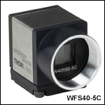
Frame rate and resolution (spot count) depend on the MLA, software-selectable active area, and operation mode.
- Square 11.26 mm x 11.26 mm Max Aperture
- 2048 x 2048 Pixel Max Camera Resolution
- One Mounted Microlens Array Included with Each WFS
- Chrome Mask or AR Coating
- 150 µm Pitch Arrays Have 73 x 73 Active Lenslets (Max)
- 300 µm Pitch Array Has 35 x 35 Active Lenslets (Max)
- User-Selectable Software Settings Control Frame Rate and Resolution
- Pupil Size Adjustment
- Operation in Normal or Faster Subsampling (sub2) Mode
- Software Controlled via Thorlabs' or User-Developed Application
Each of these Wavefront Sensors (WFS) is calibrated for use with the included mounted microlens array (MLA). A USB 3.0 interface to a PC running the software application is required to provide specified performance (see the Specs tab); however, these instruments can be operated with reduced performance via a USB 2.0 interface. Each WFS includes a bottom-mounted adapter plate with an 8-32 (M4) and a 1/4"-20 (M6) tap for mounting the sensor head on Ø1/2" posts.
Kits, available below, include two MLAs calibrated for the sensor head. If a MLA has not been factory-calibrated for use with a particular sensor head, it should not be used. Contact Tech Support to upgrade a WFS for use with additional MLAs.
| Large-Aperture Wavefront Sensorsa | |||
|---|---|---|---|
| Item # | |||
| Wavelength Range | 300 - 1100 nm | 400 - 900 nm | |
| Effective Focal Length | 4.1 mm | 5.2 mm | 14.6 mm |
| Lenslet Array Coating | Chrome Mask | AR Coated | |
| Lenslet Pitch | 150 µm | 300 µm | |
| Wavefront Accuracy (at 633 nm) | λ/25 rms | λ/30 rms | λ/40 rms |
| Wavefront Sensitivity (at 633 nm) | λ/80 rms | λ/100 rms | λ/120 rms |
| Frame Rate | 8 - 98 fps | 10 - 98 fps | |
| Camera Resolution | 2048 x 2048 Pixels Max, Software Selectable | ||
| High-Speed Control Box with PoCL and Table Clamps |
- | ||
| Included Cable | USB 3.0 Type-A to Mini-B Cable, 3 m | ||
Part Number | Description | Price | Availability |
|---|---|---|---|
WFS40-5C/M | Shack-Hartmann WFS, 11.26 mm Square Aperture, 150 µm Pitch, Chrome Masked MLA, 300 - 1100 nm, Metric Taps | $6,172.54 | 3-5 Days |
WFS40-7AR/M | Shack-Hartmann WFS, 11.26 mm Square Aperture, 150 µm Pitch, AR Coated MLA, 400 - 900 nm, Metric Taps | $6,172.54 | 3-5 Days |
WFS40-14AR/M | Shack-Hartmann WFS, 11.26 mm Square Aperture, 300 µm Pitch, AR Coated MLA, 400 - 900 nm, Metric Taps | $6,172.54 | 3 Weeks |
WFS40-5C | Shack-Hartmann WFS, 11.26 mm Square Aperture, 150 µm Pitch, Chrome Masked MLA, 300 - 1100 nm, Imperial Taps | $6,172.54 | 3-5 Days |
WFS40-7AR | Shack-Hartmann WFS, 11.26 mm Square Aperture, 150 µm Pitch, AR Coated MLA, 400 - 900 nm, Imperial Taps | $6,172.54 | 3-5 Days |
WFS40-14AR | Shack-Hartmann WFS, 11.26 mm Square Aperture, 300 µm Pitch, AR Coated MLA, 400 - 900 nm, Imperial Taps | $6,172.54 | Lead Time |
Large-Aperture Wavefront Sensor Kits

- Includes Large-Aperture Wavefront Sensor and an Additional 300 µm Pitch AR-Coated MLA
- MLAs Factory Calibrated for Use with the Included Hardware
- WFS40-K1(/M) Can Be Configured as:
- WFS40-5C(/M) by Installing the MLA with 150 µm Pitch and Chrome Mask
- WFS40-14AR(/M) by Installing the MLA with 300 µm Pitch and AR Coating
- WFS40-K2(/M) Can Be Configured as:
- WFS40-7AR(/M) by Installing the MLA with 150 µm Pitch and AR Coating
- WFS40-14AR(/M) by Installing the MLA with 300 µm Pitch and AR Coating
- Each Kit Includes a Pickup Tool Used to Easily Exchange the Installed MLA
These wavefront sensor kits come with all of the same specifications and hardware as the WFS40-5C(/M) and WFS40-7AR(/M) sold above, but they include another factory-calibrated 300 µm pitch, AR-Coated microlens array and a tool to facilitate the easy exchange of these arrays in their patented, precision magnetic holders. Information about these wavefront sensors in the Specs and Selection Guide tabs above are given by the Item # of the configuration, rather than the Item # of the kit. For example, Item # WFS40-14AR should be referenced for the case of the 300 µm pitch MLA installed on a WFS40-K1. If a MLA has not been factory-calibrated for use with a particular sensor head, it should not be used. Contact Tech Support to upgrade a WFS for use with additional MLAs.
Part Number | Description | Price | Availability |
|---|---|---|---|
WFS40-K1/M | WFS Kit with 11.26 mm Square Aperture; 150 µm Pitch, Chrome-Masked MLA and 300 µm Pitch, AR-Coated MLA; Metric Taps | $7,104.24 | Lead Time |
WFS40-K2/M | WFS Kit with 11.26 mm Square Aperture; Two AR-Coated MLAs, 150 µm Pitch and 300 µm Pitch; Metric Taps | $7,104.24 | 3 Weeks |
WFS40-K1 | WFS Kit with 11.26 mm Square Aperture; 150 µm Pitch, Chrome-Masked MLA and 300 µm Pitch, AR-Coated MLA; Imperial Taps | $7,104.24 | Lead Time |
WFS40-K2 | WFS Kit with 11.26 mm Square Aperture; Two AR-Coated MLAs, 150 µm Pitch and 300 µm Pitch; Imperial Taps | $7,104.24 | Lead Time |
High-Speed Wavefront Sensors

Click to Enlarge
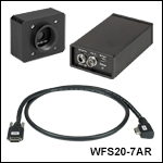
Frame rate and resolution depend on the MLA, software-selectable active area, and operation mode.
- Rectangular 7.20 x 5.40 mm Max Aperture
- 1440 x 1080 Pixel Max Camera Resolution
- One Mounted Microlens Array Included with Each WFS
- Chrome Mask or AR Coating
- 150 µm Pitch Arrays Have 47 x 35 Active Lenslets (Max)
- 300 µm Pitch Array Has 23 x 17 Active Lenslets (Max)
- User-Selectable Software Settings Control Frame Rate and Resolution
- Pupil Size Adjustment
- Operation in Normal, 2x2 Binning (Bin 2), or High-Speed Mode
- Software Controlled via Thorlabs' or User-Developed Application
These WFS include a separate control box that connects to the sensor head with the included cable. During high-speed mode operation, the field-programmable gate array (FPGA) built into the control box processes the image data and sends only the calculated spot centroid coordinates to the PC. In contrast, the entire image is sent to the PC when the WFS operates in normal and Bin 2 modes. A USB 2.0 interface to a PC running the software application is required for operation. Each WFS has three 8-32 (M4) taps on the bottom of the housing for mounting on Ø1/2" posts and four 4-40 taps on the front face for compatibility with Thorlabs' 30 mm Cage Systems.
Kits, available below, include two MLAs calibrated for the sensor head. If a MLA has not been factory-calibrated for use with a particular sensor head, it should not be used. Contact Tech Support to upgrade a WFS for use with additional MLAs.
| High-Speed Wavefront Sensorsa | |||
|---|---|---|---|
| Item # | |||
| Wavelength Range | 300 - 1100 nm | 400 - 900 nm | |
| Effective Focal Length | 4.1 mm | 5.2 mm | 14.6 mm |
| Lenslet Array Coating | Chrome Mask | AR Coated | |
| Lenslet Pitch | 150 µm | 300 µm | |
| Wavefront Accuracy (at 633 nm) | λ/30 rms | λ/60 rms | |
| Wavefront Sensitivity (at 633 nm) | λ/100 rms | λ/200 rms | |
| Frame Rate | 23 - 880 fps | 28 - 1120 fps | |
| Camera Resolution | 1440 x 1080 Pixels Max, Software Selectable | ||
| High-Speed Control Box with PoCL and Table Clamps |
 |
||
| Included Cable | USB 2.0 Type-A to Mini-B Cable, 2 m | ||
Part Number | Description | Price | Availability |
|---|---|---|---|
WFS20-5C/M | Fast Shack-Hartmann WFS, 150 µm Pitch, Chrome Masked, 300 - 1100 nm, M4 Taps | $7,175.05 | 3-5 Days |
WFS20-7AR/M | Fast Shack-Hartmann WFS, 150 µm Pitch, AR Coated: 400 - 900 nm, M4 Taps | $7,175.05 | 3-5 Days |
WFS20-14AR/M | Fast Shack-Hartmann WFS, 300 µm Pitch, AR Coated: 400 - 900 nm, M4 Taps | $7,175.05 | Lead Time |
WFS20-5C | Fast Shack-Hartmann, WFS, 150 µm Pitch, Chrome Masked, 300 - 1100 nm, 8-32 Taps | $7,175.05 | 3-5 Days |
WFS20-7AR | Fast Shack-Hartmann WFS, 150 µm Pitch, AR Coated: 400 - 900 nm, 8-32 Taps | $7,175.05 | 3-5 Days |
WFS20-14AR | Fast Shack-Hartmann WFS, 300 µm Pitch, AR Coated: 400 - 900 nm, 8-32 Taps | $7,175.05 | 3-5 Days |
High-Speed Wavefront Sensor Kits
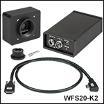
- Includes a High-Speed Wavefront Sensor, an Additional 300 µm Pitch AR-Coated MLA, and Control Box
- MLAs Factory Calibrated for Use with the Included Hardware
- WFS20-K1(/M) Can Be Configured as:
- WFS20-5C(/M) by Installing the MLA with 150 µm Pitch and Chrome Mask
- WFS20-14AR(/M) by Installing the MLA with 300 µm Pitch and AR Coating
- WFS20-K2(/M) Can Be Configured as:
- WFS20-7AR(/M) by Installing the MLA with 150 µm Pitch and AR Coating
- WFS20-14AR(/M) by Installing the MLA with 300 µm Pitch and AR Coating
- Each Kit Includes a Pickup Tool Used to Easily Exchange the Installed MLA
These wavefront sensor kits come with all of the same specifications and hardware as the WFS20-5C(/M) and WFS20-7AR(/M) sold above, but they include another factory-calibrated 300 µm pitch, AR-Coated microlens array and a tool to facilitate the easy exchange of these arrays in their patented, precision magnetic holders. Information about these wavefront sensors in the Specs and Selection Guide tabs above are given by the Item # of the configuration, rather than the Item # of the kit. For example, Item # WFS20-14AR should be referenced for the case of the 300 µm pitch MLA installed on a WFS20-K1. If a MLA has not been factory-calibrated for use with a particular sensor head, it should not be used. Contact Tech Support to upgrade a WFS for use with additional MLAs.
Part Number | Description | Price | Availability |
|---|---|---|---|
WFS20-K1/M | Fast WFS Kit with 150 µm Pitch, Chrome-Masked and 300 µm Pitch, AR-Coated Microlens Arrays, Metric, M4 Taps | $8,149.15 | Lead Time |
WFS20-K2/M | Fast WFS Kit with 150 µm Pitch and 300 µm Pitch AR-Coated Microlens Arrays, M4 Taps | $8,149.15 | 3-5 Days |
WFS20-K1 | Fast WFS Kit with 150 µm Pitch, Chrome-Masked and 300 µm Pitch, AR-Coated Microlens Arrays, 8-32 Taps | $8,149.15 | 3 Weeks |
WFS20-K2 | Fast WFS Kit with 150 µm Pitch and 300 µm Pitch AR-Coated Microlens Arrays, 8-32 Taps | $8,149.15 | Lead Time |
USB and Trigger Cables
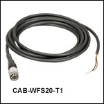
The CAB-WFS20-T1 cable is designed to connect a user-supplied external trigger source to the High-Speed Shack-Hartmann Wavefront Sensors (Item # Prefix WFS20). The CAB-DCU-T3 cable provides the same functionality for the General-Purpose and Large-Aperture Shack-Hartmann Wavefront Sensors (Item # Prefix WFS31 and WFS40, respectively). For trigger input specifications, please see the Specs tab above.
| Item # | CAB-WFS20-T1 |  |
Pin | Assignment | |
|---|---|---|---|---|---|
 Click to Enlarge |
Connector Device Side | 4-Pin Hirose, Female | 1 | Not Used | |
| TTL Trigger Input | Bare Wire (Brown) | 2 | Trigger Input Ground (Black, Bare Wire) | ||
| Shielding | None | 3 | TTL Trigger Input (Brown, Bare Wire) | ||
| Length | 2 m | 4 | Not Used | ||
| Item # | CAB-DCU-T3 |  |
Pin | Assignment | |
|---|---|---|---|---|---|
 Click to Enlarge |
Connector Device Side | Hirose HR25-7TP-8S, Female | 1 | Ground (Gray) | |
| End Opposite Connectors | Tinned End of Wires | 2 | Flash Outputa - (Green) | ||
| Function | GPIO | 3 | GPIO 1, 3.3 V LVCMOS (Blue) | ||
| Trigger In (Bare Wire) | Yes | 4 | Trigger Inputa - (Brown) | ||
| Flash & Digital Out (Bare Wire) | Yes | 5 | Flash Outputa + (Yellow) | ||
| Cable Type | Shielded High-Flexible Control Cable 8 x 0.1 mm, Ø5.0 mm |
6 | GPIO 2, 3.3 V LVCMOS (Red) | ||
| Shielding | Single Shielded | 7 | Trigger Inputa + (White) | ||
| Length | 2 m | 8 | Output Supply Voltage, 5 V (100 mA) (Pink) | ||
Part Number | Description | Price | Availability |
|---|---|---|---|
CAB-WFS20-T1 | Trigger Cable for WFS20 Wavefront Sensors | $83.75 | 3-5 Days |
CAB-DCU-T3 | Trigger and I/O Cable, Hirose 25, for DCC3240, DCC3260, WFS31 and WFS40, 2 m | $113.96 | 3-5 Days |
Kinematic Mount for Wavefront Sensors
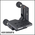
This animation shows how to convert between the right- and left-handed orientations for the KM100WFS. A similar process can be followed for the KM200PM(/M).
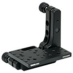
Click to Enlarge
The KM200PM mount platform's larger size allows for flexible mounting options.
| Platform Specifications | |||
|---|---|---|---|
| Item # | Tapped Holes | Through Holes | Platform Deptha |
| KM100WFS | - | #8 (x2) M3 (x3) |
1.52" (38.6 mm) |
| KM200PM | 6-32 (x16) 8-32 (x4) |
#8 (x2) | 2.10" (53.3 mm) |
| KM200PM/M | M4 (x21) | M4 (x2) | 53.3 mm (2.10") |
- Two 80 TPI Adjusters for ±4° of Fine Tip and Tilt Control
- 8 mrad Adjustment per Revolution
- Platform can be Removed and Secured to Either Arm Enabling Left- or Right-Handed Configuration
- Removable Knobs Expose Adjuster Screws with Hex Socket
Thorlabs' KM100WFS and KM200PM(/M) Kinematic Platform Mounts provide kinematic control for our CMOS-Based Shack-Hartmann Wavefront Sensors. Please note that the optical axis of the sensors will not be centered over the optical post. The animation to the right shows how to convert between the left- and right-handed orientations for the KM100WFS. This process is very similar for the KM200PM(/M).
The KM100WFS is designed to accommodate the WFS20 wavefront sensors, and features a similar design to our KM100PM platform. The WFS20 high-speed sensors can be mounted using the two #8 through holes near the front edge of the plate and the included 8-32 screws. The DCU CCD Cameras and the WFS20 sensors can also be mounted on the KM100WFS.
The KM200PM(/M) mount is larger than the KM100WFS, and can mount the WFS20 sensors using the two #8 (M4) through holes near the front edge of the plate. WFS30 and WFS40 can be mounted using one of the 8-32 tapped mounting holes. The larger profile and number of holes provides a variety of mounting options. The platform is secured to the front plate using two 4-40 screws with a 3/32" hex [the KM200PM/M uses M2.5 screws with a 2 mm (5/64") hex]. The two pieces of the mounting platform assembly are held together with two 3-48 screws [5/64" (2 mm) hex]. If desired, the mounting plate can also be removed and replaced with a user-supplied alternative, enabling custom mounting options.
Part Number | Description | Price | Availability |
|---|---|---|---|
KM200PM/M | Kinematic Prism Mount, 54.4 mm Deep, M4 Taps | $140.17 | 3-5 Days |
KM100WFS | Kinematic Mount for Thorlabs' Wavefront Sensors | $97.11 | 3-5 Days |
KM200PM | Kinematic Prism Mount, 2.14" Deep, 6-32 and 8-32 Taps | $140.17 | 3-5 Days |

