

Polaris® Kinematic Mirror Mounts with Piezoelectric Adjusters
- Designed for Long-Term Stability
- Minimal Temperature-Dependent Hysteresis
- Sapphire Adjuster Seats Prevent Wear Over Time
- Each Actuator Contains Internal Piezo Element for Fine Adjustment
POLARIS-K05P2
Ø1/2" Mirror Mount
POLARIS-K1S3P
Ø1" Mirror Mount,
3 Adjusters
POLARIS-K2S2P
Ø2" Mirror Mount
OVERVIEW
| Key Specificationsa | |||
|---|---|---|---|
| Item # Suffix | -K05P2 | -K1S2P -K1S3P |
-K2S2P |
| Optic Size | Ø1/2" | Ø1" | Ø2" |
| Optic Thickness (Min) | 0.08" (2 mm) | 0.14" (3.5 mm) | |
| Mechanical Angular Range | ±5° | ±4° | ±3.4° |
| Piezoelectric Angular Range | >490 µrad | >500 µrad | >280 µrad |
| Adjusters | Manually Adjustable 100 TPI Screws with Integrated Piezoelectric Elements |
||
| Piezo Control Voltage | 0 to 150 V | ||
| Piezo Connectors | Male SMB (SMB-to-BNC Cables Included) |
||
| Beam Deviation after Temperature Cyclingb |
<6 µrad | <1 µrad | <2 µrad |
| Mounting | Two #8 (M4) Counterbores | Four #8 (M4) Counterbores |
|
| Compatible Piezo Controllers |
MDT693B Three-Axis Benchtop Controller MDT694B Single-Axis Benchtop Controllerc KPC101 Single-Axis K-Cube® Piezo Controller and Strain Gauge Readerc,d |
||
Features
- Machined from Heat-Treated Stainless Steel with Low Coefficient of Thermal Expansion (CTE)
- Fully Integrated Piezoelectric Elements Provide Step Sizes Down to 0.5 µrad
- Matched Actuator and Back Plate Provide Smooth Manual Kinematic Adjustment
- Hardened Stainless Steel Ball Contacts with Sapphire Seats for Durability and Smooth Movement
- Passivated Stainless Steel Surface Ideal for Vacuum and High-Power Laser Cavity Applications
- Extensive Testing Guarantees Less than 6 μrad Deviation After 15 °C Temperature Cycling (See Test Data Tab)
- Custom Mount Configurations are Available by Contacting Tech Sales
The Polaris® Kinematic Mirror Mounts with Piezoelectric Adjusters are the ultimate solution for applications requiring stringent, actively monitored, long-term alignment stability. We recommend driving the piezo actuators using our benchtop or Kinesis® K-Cube® piezo controllers.
Replacement piezoelectric adjusters for the mounts are also available separately below.
Optic Retention
These Polaris mounts use either a monolithic flexure arm or a flexure spring and setscrew combination to hold the optic. These designs provide high holding force and pointing stability with minimal optic distortion. For more details, see the Test Data tab.
Polaris optic bores are precision machined to achieve a fit that will provide optimum beam pointing stability performance over changing environmental conditions such as temperature changes, transportation shock, and vibration. These mounts are not designed to be used with optics that have an outer diameter tolerance greater than +0/-0.1 mm, such as metric mirror sizes (Ø12.5 mm, Ø25 mm, or Ø50 mm). To order a mount designed for metric optics, please contact Tech Sales.
Design
Machined from heat-treated stainless steel, Polaris mounts utilize precision-matched adjusters with ball contacts and sapphire seats to provide smooth kinematic adjustment. As shown on the Test Data tab, these mounts have undergone extensive testing to ensure high-quality performance. The Polaris design addresses all of the common causes of beam misalignment; please refer to the Design Features tab for more information.
Our design incorporates high-adjustment-sensitivity piezoelectric stacks directly into the hardened stainless steel adjusters, enabling smooth coarse and fine movements along each axis. When used in an external feedback loop, as illustrated on the Applications tab, these mounts combine the exceptional thermal stability of our standard Polaris kinematic mirror mounts with the ability to actively correct the beam pointing. Like all Polaris mounts, they are machined from heat-treated stainless steel, utilize precision-matched adjusters, and incorporate ball contacts and sapphire seats at all contact points.
Each Polaris piezo mount utilizes snap-on SMB connectors. This model is specifically designed to minimize cable twisting as the mount is actuated. Furthermore, the design of SMB cables prevents incidental movement of the mirror when the cord is attached. One 36" SMB-to-BNC cable per axis is included with each piezo mount sold below. If different cable lengths or connctors are desired, additional SMB cable configurations can be purchased separately below. Please note that the piezo actuators do not include a strain gauge.
Post Mounting
The Polaris mirror mounts are equipped with #8 (M4) counterbores for post mounting. Select mounts also include Ø2 mm alignment pin holes around the mounting counterbore, allowing for precision alignments when paired with our posts for Polaris mirror mounts. See the Usage Tips tab for more recommendations about mounting configurations.
Vacuum Compatibility
All Polaris mounts on this page are designed to be compatible with cleanroom and vacuum applications. See the Specs tab and the Design Features tab for details.
SPECS
| Item # | POLARIS-K05P2 | POLARIS-K2S2P | ||
|---|---|---|---|---|
| Optic Specifications | ||||
| Optic Sizesa | Ø1/2" | Ø1" | Ø2" | |
| Optic Thickness (Min) | 0.08" (2 mm) | 0.14" (3.5 mm) | 0.14" (3.5 mm) | |
| Optic Mounting Torque (Recommended) | 6 to 10 oz-in for 6 mm Thick Optics | 5 to 7 oz-in for 6 mm Thick Optics | 4 to 6 oz-in for 12 mm Thick Optics | |
| Beam Deviation after Temperature Cyclingb | <6 µrad | <1 µrad | <2 µrad | |
| Adjuster Specifications | ||||
| Number of Adjusters | 2 | 3 | 2 | 2 |
| Angular Range | Mechanical: ±5° Piezo: >490 µrad |
Mechanical: ±4° Piezo: >500 µrad |
Mechanical: ±3.4° Piezo: >280 µrad |
|
| Angular Resolution | Mechanical: ~14 mrad/rev Piezo: ~0.5 µrad for a 0.1 V Stepc |
Mechanical: ~7.7 mrad/rev Piezo: ~0.5 µrad for a 0.1 V Stepc |
Mechanical: ~4.75 mrad/rev Piezo: ~0.18 µrad for a 0.1 V Stepc |
|
| Adjusters | Manually Adjustable 100 TPI Screws with Integrated Piezoelectric Elements and Matched Actuator/Body Pairs |
|||
| Piezo Control Voltage | 0 to 150 V | |||
| Piezo Connectors | Male SMB (One SMB-to-BNC Cable Included for Each Adjuster) |
|||
| Compatible Piezo Controllers | MDT693B Three-Axis Benchtop Controller MDT694B Single-Axis Benchtop Controllerd KPC101 Single-Axis K-Cube® Controller and Strain Gauge Readerd,e |
|||
| Physical Specifications | ||||
| Mounting | Two #8 (M4) Counterbores | Four #8 (M4) Counterbores | ||
| Alignment Pin Holes | Two Ø2 mm Holes for DIN 7-m6 Ground Dowel Pins at Each Counterbore | Two Ø2 mm Holes for DIN 7-m6 Ground Dowel Pins at Each Mounting Face | ||
| Vacuum Compatibility | 10-5 Torr at 20 °C Epoxy Meets Low Outgassing Standards NASA ASTM E595, Telcordia GR-1221 |
10-9 Torr at 25 °C with Proper Bake Out 10-5 Torr at 25 °C without Bake Out Grease Vapor Pressure: 10-13 Torr at 20 °C; 10-5 Torr at 200 °C |
||
| Operating Temperature | -25 °C to 130 °C | -25 to 85 °C | ||
TEST DATA
Polaris® Mirror Mount Test Data
Polaris Kinematic Mirror Mounts undergo extensive testing to ensure high-quality performance.
After mounting the Polaris to a Ø1" stainless steel post, the mirror and post assembly was secured to a stainless steel optical table in a temperature-controlled environment. The mirror was secured using the flexure spring, not glued; see the Usage Tips tab for additional mounting recommendations. A beam from an independently temperature-stabilized laser diode was reflected by the mirror onto a position sensing detector.
Angular Tuning Range of Piezoelectric Adjusters
Purpose: This test was done to determine the full adjustable range of the piezoelectric stack inside the adjuster screw.
Procedure: Each axis was connected to one of our previous-generation KPZ101 Single-Channel K-Cube® Piezo Controllers (set in manual mode) or to a single channel on our MTD693B Three-Axis Benchtop Controller. The voltage was increased from 0 to 150 V, the maximum control voltage, in 5 V steps (blue line). Then the voltage was decreased from 150 V to 0 V, again using 5 V steps (red line).
Results: The maximum deflection that can be imparted by the piezoelectric stack is shown in the plots in Figures 3.1 through 3.6. This maximum deflection is >490 µrad for the Ø1/2" mount, >500 µrad for the Ø1" mounts, and >280 µrad for the Ø2" mounts. The well-known hysteresis response of piezoelectric materials is also evident. That is, the displacement at a given voltage depends upon whether the applied voltage is increasing or decreasing.
| Ø1/2" Piezoelectric Mount Angular Adjustment |
|---|
 Click to Enlarge Figure 3.1 Change in Yaw from Piezo Control Voltage for Ø1/2" Piezoelectric Mirror Mount  Click to Enlarge Figure 3.2 Change in Pitch from Piezo Control Voltage for Ø1/2" Piezoelectric Mirror Mount |
| Ø1" Piezoelectric Mounts Angular Adjustment |
|---|
 Click to Enlarge Figure 3.3 Change in Yaw from Piezo Control Voltage for Ø1" Piezoelectric Mirror Mount  Click to Enlarge Figure 3.4 Change in Pitch from Piezo Control Voltage for Ø1" Piezoelectric Mirror Mount |
| Ø2" Piezoelectric Mount Angular Adjustment |
|---|
 Click to Enlarge Figure 3.5 Change in Yaw from Piezo Control Voltage for Ø2" Piezoelectric Mirror Mount  Click to Enlarge Figure 3.6 Change in Pitch from Piezo Control Voltage for Ø2" Piezoelectric Mirror Mount |
Positional Repeatability After Thermal Shock
Purpose: This testing was done to determine how reliably the mount returns the mirror to its initial position so that the alignment of the optical system is unaffected by the temperature shock.
Procedure: The ambient temperature was raised by 15 °C over a period of at least 45 minutes. Then the temperature was allowed to return to near room temperature. During these tests, the piezo actuators were not connected to a voltage source. The worst-case results obtained by this method are shown below.
Results: The thermal shock data for each Polaris mount is shown in the plots in Figures 3.7 through 3.12. As shown in the plots, when the Polaris mount was returned to its initial temperature, the mirror position returned to within 6 µrad of its initial position for the Ø1/2" mount, within 1 µrad for the Ø1" mounts, and within 2 µrad for the Ø2" mount.
For Comparison: To get a 1 µrad change in the mount's position, the 100 TPI adjuster on the Ø1/2" Polaris mount needs to be rotated by only 0.025° (1/14 400 of a turn). A highly skilled operator might be able to make an adjustment as small as 0.3° (1/1200 of a turn), which corresponds to a 12 µrad change in the mount's position.
Conclusions: These Polaris mirror mounts are high-quality, ultra-stable mounts that will reliably return a mirror to within several µrad of its original position after cycling through a temperature change in an open-loop setup. With a large adjustable range on each axis and a typical step size of 0.5 µrad (for a 0.1 V change in applied voltage), the Polaris mounts are capable of providing sub-µrad alignment stability in a closed-loop setup, even under punishing experimental conditions.
| Ø1/2" Piezoelectric Mount Thermal Shock |
|---|
 Click to Enlarge Figure 3.7 Thermal Repeatability for POLARIS-K05P2 Mirror Mount |
 Click to Enlarge Figure 3.8 This plot shows the final angular position of a second POLARIS-K05P2 for 20 consecutive thermal shock tests. The change in temperature is the difference between the starting temperature and the temperature at the end of the test and includes factors such as the variation in room temperature. This shows the repeatability of the tests. |
| Ø1" Piezoelectric Mounts Thermal Shock |
|---|
 Click to Enlarge Figure 3.9 Thermal Repeatability for POLARIS-K1S3P Mirror Mount |
 Click to Enlarge Figure 3.10 This plot shows the final angular position of a second POLARIS-K1S3P for 10 consecutive thermal shock tests. The change in temperature is the difference between the starting temperature and the temperature at the end of the test and includes factors such as the variation in room temperature. This shows the repeatability of the tests. |
| Ø2" Piezoelectric Mount Thermal Shock |
|---|
 Click to Enlarge Figure 3.11 Thermal Repeatability for POLARIS-K2S2P Mirror Mount |
 Click to Enlarge Figure 3.12 The plot above shows the final angular position of a second POLARIS-K2S2P for 10 consecutive thermal shock tests. The change in temperature is the difference between the starting temperature and the temperature at the end of the test and includes factors such as the variation in room temperature. This shows the repeatability of the tests. |
APPLICATION

Click for Details
Figure 4.1 Polaris Kinematic Mirror Mount as Part of a Closed-Loop System
Polaris® Mirror Mount in a Beam Stabilization Setup
Active beam stabilization is often used to compensate for beam drift (unintended beam pointing deviations) in experimental setups. Drift can be caused by insecurely mounted optics, laser source instabilities, and thermal fluctuations within an optomechanical setup. In addition to correcting for setup errors, active stabilization is frequently used in laser cavities to maintain a high output power or used on an optical table to ensure that long measurements will take place under constant illumination conditions. Setups with long beam paths also benefit from active stabilization, since small angular deviations in a long path will lead to significant displacements downstream.
An example of a beam stabilization setup is shown in Figure 4.1. A beamsplitter inserted in the optical path sends a sample of the beam to a position sensor that monitors the displacement of the beam relative to the detector's center. (For optimal stabilization, the beamsplitter should be as close as possible to the measurement.) The position detector outputs an error signal in X and Y that is proportional to the beam's position. Each error signal is fed into a channel of a piezoelectric controller that steers the beam back to the center of the sensor.
The setup illustrated here stabilizes the beam to a point in space. In order to stabilize the beam over a beam path (i.e., over two points in space), two piezoelectric mirror mounts, as well as the associated electronics, are required. Suggested electronics for a beam stabilization setup are given in Table 4.2.
| Table 4.2 Suggested Components | |
|---|---|
| Description | Item # |
| Polaris Mirror Mount with Piezo Adjusters (Choose One) |
POLARIS-K05P2, POLARIS-K1S3P, POLARIS-K1S2P, or POLARIS-K2S2P |
| Piezoelectric Controller (Choose One) |
MDT693B Three-Axis Benchtop Controller, MDT694B Single-Axis Benchtop Controllera, or KPC101 Single-Axis K-Cube® Controller and Strain Gauge Readera,b |
| Position Sensor (Choose One) |
PDP90A (320 - 1100 nm), PDQ80A (400 - 1050 nm), or PDQ30C (1000 - 1700 nm) |
| K-Cube Position Sensor Controller | KPA101 |
DESIGN FEATURES

Click to Enlarge
Figure 5.1 Details of the Polaris Design. The POLARIS-K05P2 uses a flexure spring and setscrew combination instead of the monolithic retention arm shown here.
Several common factors typically lead to beam misalignment in an optical setup. These include temperature-induced hysteresis of the mirror's position, crosstalk, drift, and backlash. Polaris mirror mounts are designed specifically to minimize these misalignment factors and thus provide extremely stable performance. Hours of extensive research, multiple design efforts using sophisticated design tools, and months of rigorous testing went into choosing the best components to provide an ideal solution for experiments requiring ultra-stable performance from a kinematic mirror mount.
Thermal Hysteresis
The temperature in most labs is not constant due to factors such as air conditioning, the number of people in the room, and the operating states of equipment. Thus, it is necessary that all mounts used in an alignment-sensitive optical setup be designed to minimize any thermally induced alignment effects. Thermal effects can be minimized by choosing materials with a low coefficient of thermal expansion (CTE), like stainless steel. However, even mounts made from a material with a low CTE do not typically return the mirror to its initial position when the initial temperature is restored. All the critical components of the Polaris mirror mounts are heat treated prior to assembly since this process removes internal stresses that can cause a temperature-dependent hysteresis. As a result, the alignment of the optical system will be restored when the temperature of the mirror mount is returned to the initial temperature.
The method by which the mirror is secured in the mount is another important design factor for the Polaris; these Polaris mounts offer excellent performance without the use of adhesives. Instead, they use a monolithic retention arm or a flexure spring that is pressed onto the edge of the mirror using a setscrew. Setscrews, when used by themselves to hold an optic, tend to move as the temperature changes. In contrast, the holding force provided by the Polaris design is sufficient to keep the mirror locked into place regardless of the ambient temperature.
Crosstalk
Crosstalk is minimized by carefully controlling the dimensional tolerances of the front and back plates of the mount so that the pitch and yaw actuators are orthogonal. In addition, sapphire seats are used at all three contact points. Standard metal-to-metal actuator contact points will wear down over time. The polished sapphire seats of the Polaris mounts, in conjunction with the hardened stainless steel actuator tips, maintain the integrity of the contact surfaces over time.
Drift and Backlash
In order to minimize the positional drift of the mirror mount and backlash, it is necessary to limit the amount of play in the adjuster as well as the amount of lubricant used. When an adjustment is made to the actuator, the lubricant will be squeezed out of some spaces and built up in others. This non-equilibrium distribution of lubricant will slowly relax back into an equilibrium state. However, in doing so, this may cause the position of the front plate of the mount to move. The Polaris mounts use adjusters matched to the body that exceed all industry standards so very little adjuster lubricant is needed. As a result, alignment of the Polaris mounts is extremely stable even after being adjusted (see the Test Data tab for more information). In addition, these adjusters have a smooth feel that allows the user to make small, repeatable adjustments.
Integrated Piezoelectric Stacks
Each adjuster screw incorporates a piezoelectric stack inside the body of the actuator, seated directly behind the tip. This in-line design keeps the number of ball contact points to a minimum, reduces the number of moving parts, and ensures that the low crosstalk guaranteed by our precision-machined components is not compromised. Whether being moved by hand or by the piezoelectric stack, the adjusters make use of the same sapphire-to-hardened-steel contact points to provide precise motion for the life of the mount.
Compatible with Vacuum Environments
Each component has been carefully selected to ensure vacuum compatibility. The epoxy used to bond the sapphire seats in place is baked using a NASA-approved low-outgassing procedure. DuPont LVP High-Vacuum (Krytox) Grease, an ultra-high-vacuum-compatible, low-outgassing PTFE grease is used with the adjusters. The piezoelectric stack is sheathed by a thin, low-solvent-content acrylic material that supports vacuum environments down to at least 10-5 Torr. For the piezo connector, we chose PTFE, a non-hygroscopic plastic, as the insulating layer. All electrical contacts are made by a low-flux solder; the flux is burned off during the soldering process.
Please note that a high-voltage, coaxial feedthrough vacuum flange is required to pass the piezo control voltage into vacuum.
USAGE TIPS
Click to Enlarge
Figure 6.1 Optic distortion of a BB1-E02 mirror mounted in a Ø1" Polaris mount. At zero torque, the sample mirror's flatness was λ/10 over the clear aperture
(λ = 633 nm). The shaded region indicates the recommended amount of torque.
Through thermal changes and vibrations, the Polaris kinematic mirror mounts are designed to provide years of use. Below are some usage tips to ensure that the mount provides optimal performance.
General Usage Tips
Match Materials
Due to its relatively low coefficient of thermal expansion, stainless steel was chosen as the material from which to fabricate the Polaris mount. When mounting the Polaris, we recommend using components fabricated from the same material.
Use a Wide Post
The Polaris' performance is optimized for use with a Ø1" post for Polaris mounts. These posts are made of heat-treated stainless steel and provide two planes of contact with the mount, which help confine the bottom of the mount during variations in the surrounding temperature, thereby minimizing potential alignment issues.
Optic Mounting
Since an optic is prone to movement within its mounting bore, all optics should be mounted with the Polaris out of the setup to ensure accurate mounting that will minimize misalignment effects. We recommend using a torque wrench when installing an optic in a Polaris mount. Over-torquing the flexure arm optic retainer can result in dramatic surface distortions. Figure 6.1 shows surface distortions that result from increasing torque values delivered by the TD24 Torque Wrench for the front plate used in the POLARIS-K1S3P and POLARIS-K1S2P with a Ø1", 6 mm thick BB1-E02 mirror mounted in it. The test was stopped once the distortion was greater than 0.2 waves.
Front Plate's Position
To achieve the best performance, it is recommended that the front plate be kept as parallel as possible to the back plate. This ensures the highest adjustment stability.
Mount as Close to the Table's Surface as Possible
To minimize the impact of vibrations and temperature changes, it is recommended that your setup has as low of a profile as possible. Using short posts will reduce the Y-axis translation caused by temperature variations and will minimize any movements caused by vibrations.
Polish and Clean the Points of Contact
We highly recommend that the points of contact between the mount and the post, as well as the post and the table, are clean and free of scratches or defects. For best results, we recommend using a polishing stone to clean the table’s surface and a polishing pad (Item # LF1P) for the top and bottom of the post as well as the bottom of the mount.
Piezo Usage Tips
Disconnect Unused Channels
If active stabilization of a given axis is not needed, then it is not necessary to connect the unused axis to a piezoelectric controller. Any noise on the electrical connection may cause an undesired movement in the beam.
Connect Cables only when Power Supply is Off
The piezoelectric stacks may be irreversibly damaged by abrupt changes in the applied voltage. In order to prevent such damage, ensure that the power supply is off before connecting the SMB cable.
Use Gentle Voltage Steps
Abrupt charging or discharging of the piezoelectric actuator may cause irreversible damage to the piezo.
Stay within the 0 - 150 V Control Voltage Range
Applying voltages less than 0 V (negative voltages) or greater than 150 V may cause irreversible damage to the piezo.
Handle with Care
Piezoelectrics are ceramic materials, and therefore relatively brittle as compared to common optomechanics. Hence, they are sensitive to shock forces. Do not drop the mount or place it in a box without protective cushioning.
Not Recommended
We do not recommend taking the adjusters out of the back plate, as it can contaminate the threading. This can reduce the fine adjustment performance significantly. Also, do not pull the front plate away as it might stretch the springs beyond their operating range, crack the sapphire seats, or break the piezoelectric stacks. Finally, do not overtighten the retaining screws that secure the flat spring that holds the optic in place; only slight force is required to secure the optic in place.
POLARIS FAMILY
Thorlabs offers several different general varieties of Polaris mounts, including kinematic side optic retention, SM-threaded, low optic distortion, piezo-actuated, vertical drive, and glue-in optic mounts, a fixed monolithic mirror mount and fixed optic mounts, XY translation mounts, 5-axis kinematic mount, a kinematic platform mount, and kinematic, fixed focus collimators. Refer to the tables below for our complete line of Polaris mounts, grouped by mount type, optic bore size, and then arranged by optic retention method and adjuster type (or intended application in the case of fixed mounts). We also offer a line of accessories that have been specifically designed for use with our Polaris mounts; these are listed in Table 103H. Note that the tables below list Item # suffixes that omit the "POLARIS" prefix for brevity. Click the photos below for details.
| Table 103A Polaris Mount Optic Retention Methods | |||
|---|---|---|---|
| Side Lock | SM Threaded | Low Distortion | Glue-In |
 |
 |
 |
 |
| Table 103B Polaris Mount Adjuster Types | |||||
|---|---|---|---|---|---|
| Side Hole | Hex | Adjuster Knobs | Adjuster Lock Nuts |
Piezo Adjusters | Vertical-Drive Adjusters |
 |
 |
 |
 |
 |
 |
| Table 103C Polaris Kinematic Mounts for Round Optics | ||||
|---|---|---|---|---|
| Optic Retention Method | Side Lock | SM Threaded | Low Distortion | Glue-In |
| Ø1/2" Optics | ||||
| 2 Side Hole Adjusters | - | - | - | -K05C4 -K05G4 |
| 2 Hex Adjusters | -K05S1 | -K05T1 | -K05F1 | - |
| 2 Adjusters with Lock Nuts | -K05S2 | -K05T2 | -K05F2 | - |
| 2 Piezoelectric Adjusters | -K05P2 | - | - | - |
| 2 Vertical Adjusters | -K05VS2 -K05VS2L |
- | - | - |
| 3 Hex Adjusters | -K05 | - | - | - |
| 3 Adjusters with Lock Nuts | - | -K05T6 | -K05F6 | - |
| 3 Adjuster Knobs (Tip/Tilt/Z) & 2 Hex Adjusters (X/Y) |
- | -K05XY | - | - |
| Ø19 mm (3/4") Optics | ||||
| 2 Side Hole Adjusters | -K19S4 | - | -K19F4/M | -K19G4 |
| Ø25 mm Optics | ||||
| 2 Side Hole Adjusters | -K25S4/M | - | -K25F4/M | - |
| Ø1" Optics | ||||
| 2 Side Hole Adjusters | -K1S4 | - | - | -K1C4 -K1G4 |
| 2 Hex Adjusters | -K1E2 -K1-2AH |
-K1T2 | -K1F2 | - |
| 2 Adjuster Knobs | - | -K1T1 | -K1F1 | - |
| 2 Piezoelectric Adjusters | -K1S2P | - | - | - |
| 2 Vertical Adjusters | -K1VS2 -K1VS2L |
- | - | - |
| 3 Side Hole Adjuster | -K1S5 | - | - | - |
| 3 Hex Adjusters | -K1E3 -K1-H |
-K1T3 | - | - |
| 3 Adjuster Knobs | -K1E -K1 |
-K1T | -K1F | - |
| 3 Piezoelectric Adjusters | -K1S3P | - | - | - |
| 3 Adjuster Knobs (Tip/Tilt/Z) & 2 Hex Adjusters (X/Y) |
- | -K1XY | - | - |
| Optic Retention Method | Side Lock | SM Threaded | Low Distortion | Glue-In |
| Ø1.5" Optics | ||||
| 2 Side Hole Adjusters | -K15S4 | - | -K15F4 | - |
| 2 Vertical Adjusters | -K15VS2 -K15VS2L |
- | - | - |
| 3 Adjuster Knobs (Tip/Tilt/Z) & 2 Hex Adjusters (X/Y) |
- | -K15XY | - | - |
| Ø50 mm Optics | ||||
| 2 Side Hole Adjusters | -K50S4/M | - | -K50F4/M | - |
| Ø2" Optics | ||||
| 2 Hex Adjusters | -K2S2 | -K2T2 | -K2F2 | - |
| 2 Adjuster Knobs | -K2S1 | -K2T1 | -K2F1 | - |
| 2 Piezoelectric Adjusters | -K2S2P | - | - | - |
| 2 Vertical Adjusters | -K2VS2 -K2VS2L |
- | - | - |
| 3 Hex Adjusters | -K2S3 | -K2T3 | -K2F3 | - |
| 3 Adjuster Knobs | -K2 | -K2T | -K2F | - |
| Ø3" Optics | ||||
| 2 Side Hole Adjusters | -K3S4 | - | - | - |
| 3 Side Hole Adjusters | -K3S5 | - | - | - |
| Ø4" Optics | ||||
| 2 Side Hole Adjusters | - | - | -K4F4 | - |
| Ø6" Optics | ||||
| 2 Side Hole Adjusters | - | - | -K6F4 | - |
| Table 103D Polaris XY Translation Mounts for Round Optics | ||
|---|---|---|
| Optic Retention Method | SM Threaded | Representative Photos |
| Ø1/2" Optics |   |
|
| 2 Hex Adjusters (X/Y) | -05CXY | |
| -05XY | ||
| 3 Adjuster Knobs (Tip/Tilt/Z) & 2 Hex Adjusters (X/Y) |
-K05XY | |
| Ø1" Optics | ||
| 2 Hex Adjusters (X/Y) | -1XY | |
| 3 Adjuster Knobs (Tip/Tilt/Z) & 2 Hex Adjusters (X/Y) |
-K1XY | |
| Ø1.5" Optics | ||
| 2 Hex Adjusters (X/Y) & 3 Adjuster Knobs (Tip/Tilt/Z) |
-K15XY | |
| Table 103E Polaris Fixed Mounts for Round Optics | ||||||
|---|---|---|---|---|---|---|
| Optic Retention Method | Side Lock | Low Distortion |
Glue-In | Representative Photos |
||
| Ø1/2" Optics | 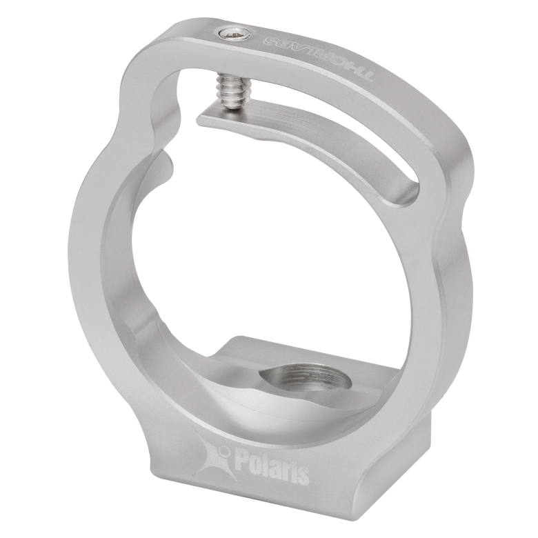    |
|||||
| Optimized for Mirrors | - | -B05F | -C05G | |||
| Optimized for Beamsplitters | -B05S | - | -B05G | |||
| Optimized for Lenses | - | - | -L05G | |||
| Ø19 mm (Ø3/4") Optics | ||||||
| Optimized for Mirrors | -19S50/M | - | - | |||
| Ø1" Optics | ||||||
| Optimized for Mirrors | - | -B1F | -C1G | |||
| Optimized for Beamsplitters | -B1S | - | -B1G | |||
| Optimized for Lenses | - | - | -L1G | |||
| Ø2" Optics | ||||||
| Optimized for Mirrors | - | -B2F | -C2G | |||
| Optimized for Beamsplitters | -B2S | - | - | |||
| Table 103F Polaris Kinematic 1.8" x 1.8" Platform Mount | ||
|---|---|---|
| Adjustment Method | Item # Suffix |  |
| 2 Adjuster Knobs | -K1M4(/M) | |
| Table 103G Polaris Kinematic, Fixed Focus Collimators | ||
|---|---|---|
| Adjustment Method | Item #s | Representative Photo |
| 2 Side Hole Adjusters | PF2F53(/M) PF2F63(/M) PF2F78(/M) PF2F85(/M) |
 |
| Table 103H Accessories for Polaris Mounts | |
|---|---|
| Description | Representative Photos |
| Ø1/2" Posts for Polaris Mounts |  |
| Ø1" Posts for Polaris Mounts | |
| Non-Bridging Clamping Arms | 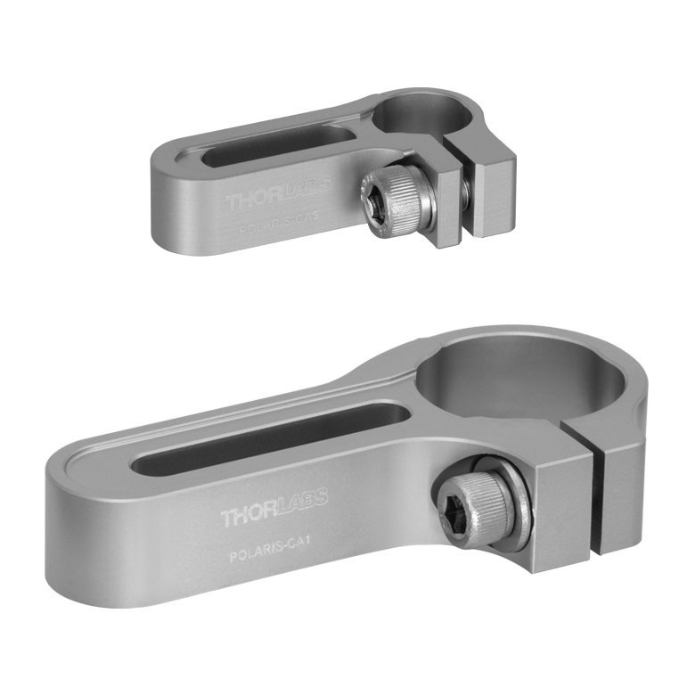 |
| 45° Mounting Adapter |  |
Ø1/2" Polaris® Kinematic Mirror Mount, 2 Piezoelectric Adjusters


- 2-Adjuster Piezoelectric and Knob-Driven Design
- Designed for Use with Ø1/2" Optics
- 100 TPI Screws with Integrated PK4DMP1 Piezoelectric Elements
- Less than 6 µrad Beam Deviation After Temperature Cycling (See the Test Data Tab)
- Two SMB-to-BNC Cables Included
This Ø1/2" Kinematic Mirror Mount with Two Piezoelectric Adjusters is designed to provide long-term alignment stability in systems with an external feedback loop. It offers exceptional angular resolution of ~0.5 µrad for a 0.1 V step via piezoelectric adjustment. We recommend driving the piezo actuators using our benchtop or Kinesis K-Cube® open-loop piezo controllers. The KPC101
The Polaris design results in greater durability and thermal performance compared to non-Polaris mirror mounts. A flexure spring and setscrew combination provides temperature-independent retention of the optic, unlike nylon-tipped setscrews that are sensitive to temperature fluctuations. The setscrew that adjusts the flexure spring accepts a 1/16" (1.5 mm) hex key. We strongly recommend using a torque driver for securing the optic to prevent optical surface distortion and to improve thermal stability.
This mirror mount comes with two adjuster lock nuts that can be tightened by holding the adjuster knob while lightly tightening the lock nut by hand or with an 11 mm thin-head, open-ended hex wrench. Lock nuts only need to be lightly tightened to a torque of approximately 4 to 8 oz-in (0.03 to 0.06 N·m). These lock nuts hold in place the manual adjustment and will not affect the fine piezoelectric adjustment of this mount. The mount is designed so that the knobs and lock nuts are flush with the bottom surface of the housing, allowing it to be directly mounted to an optical table or breadboard.
Post mounting is provided by two #8 (M4) counterbores located at right angles with respect to each other for right- or left-handed mounting. Due to the shallow design of the counterbores, low-profile 8-32 and M4 cap screws are included for mounting. Note that the M4 cap screw reduces the clear aperture to 0.415" (10.5 mm). If the impact of the cap screws on the clear aperture is a concern, please contact Tech Sales to discuss other mounting options. The 8-32 cap screw accepts a 5/64" (2 mm) hex wrench, while the M4 cap screw accepts a 2.5 mm hex wrench. For custom mounting configurations, Ø2 mm alignment pin holes are located on both sides of each counterbore for setting a precise location and mounting angle. Standard DIN 7-m6 ground dowel pins are recommended; see the Docs icon  )
)
Two PAA236R cables are included with this mount. Each of these 36" cables has a 90° SMB connector on one end and a straight BNC connector on the other. Additional cables of lengths from 12" to 72" are available below with options for cables with straight SMB to BNC male connectors or straight SMB to SMC female connectors.
Note: The POLARIS-K05P2 mount incorporates 1/4"-100 adjuster screws and is compatible only with the POLARIS-P20A actuator (sold below).
Part Number | Description | Price | Availability |
|---|---|---|---|
POLARIS-K05P2 | Polaris® Piezoelectric Ø1/2" Mirror Mount, 2 Adjusters with Lock Nuts, Cables Included | $1,030.85 | Today |
Ø1" Polaris® Kinematic Mirror Mount, 3 Piezoelectric Adjusters


- 3-Adjuster Piezoelectric and Knob-Driven Design
- Designed for Use with Ø1" Optics
- 100 TPI Screws with Integrated Piezoelectric Elements
- Less Than 1 µrad Beam Deviation After Temperature Cycling (See the Test Data Tab)
- Three SMB-to-BNC Cables Included
This Ø1" Kinematic Mirror Mount with Three Piezoelectric Adjusters is designed to provide long-term alignment stability in systems with an external feedback loop. It offers exceptional angular resolution of ~0.5 µrad for a 0.1 V step via piezoelectric adjustment. We recommend driving the piezo actuators using our benchtop or Kinesis K-Cube® open-loop piezo controllers. The KPC101
The Polaris design results in greater durability and thermal performance compared to non-Polaris mirror mounts. A monolithic retention arm provides temperature-independent retention of the optic, unlike nylon-tipped setscrews that are sensitive to temperature fluctuations. The setscrew that adjusts the flexure arm accepts a 0.05" (1.3 mm) hex key. We strongly recommend using a torque driver for securing the optic to prevent optical surface distortion and to improve thermal stability.
This mirror mount comes with three adjuster lock nuts that can be tightened by holding the adjuster knob while lightly tightening the lock nut by hand or with a TW12 Preset Torque Wrench. Lock nuts only need to be lightly tightened to a torque of approximately 4 to 8 oz-in (0.03 to 0.06 N·m). These lock nuts hold in place the manual adjustment and will not affect the fine piezoelectric adjustment of this mount.
Post mounting is provided by two #8 (M4) counterbores located at right angles with respect to each other for right- or left-handed mounting. One 8-32 cap screw and one M4 cap screw are included for securing the mount to a post. The 8-32 cap screw accepts a 9/64" hex wrench, while the M4 cap screw accepts a 3 mm hex wrench.
Three PAA236R cables are included with this mount. Each of these 36" cables has a 90° SMB connector on one end and a straight BNC connector on the other. Additional cables of lengths from 12" to 72" are available below with options for cables with straight SMB to BNC male connectors or straight SMB to SMC female connectors.
Note: The POLARIS-K1S3P mount incorporates 3/8"-100 adjuster screws and is compatible only with the POLARIS-P20 actuator (sold below).
Part Number | Description | Price | Availability |
|---|---|---|---|
POLARIS-K1S3P | Polaris® Piezoelectric Ø1" Mirror Mount, 3 Adjusters with Lock Nuts, Cables Included | $1,365.79 | Today |
Ø1" Polaris® Kinematic Mirror Mount, 2 Piezoelectric Adjusters


- 2-Adjuster Piezoelectric and Knob-Driven Design
- Designed for Use with Ø1" Optics
- 100 TPI Screws with Integrated Piezoelectric Elements
- Less Than 1 µrad Beam Deviation After Temperature Cycling (See the Test Data Tab)
- Two SMB-to-BNC Cables Included
This Ø1" Kinematic Mirror Mount with Two Piezoelectric Adjusters is similar to the 3-adjuster version sold above but features a hardened steel ball in place of the third adjuster. This mount is designed to provide long-term alignment stability in systems with an external feedback loop. It offers exceptional angular resolution of ~0.5 µrad for a 0.1 V step via piezoelectric adjustment. We recommend driving the piezo actuators using our benchtop or Kinesis K-Cube® open-loop piezo controllers. The KPC101 K-Cube Controller and Strain Gauge Reader will also require one of our BNC-to-SMC cables per axis (sold below). Please note that the piezo actuators do not include strain gauges.
The Polaris design results in greater durability and thermal performance compared to non-Polaris mirror mounts. A monolithic retention arm provides temperature-independent retention of the optic, unlike nylon-tipped setscrews that are sensitive to temperature fluctuations. The setscrew that adjusts the flexure arm accepts a 0.05" (1.3 mm) hex key. We strongly recommend using a torque driver for securing the optic to prevent optical surface distortion and to improve thermal stability.
This mirror mount comes with two adjuster lock nuts that can be tightened by holding the adjuster knob while lightly tightening the lock nut by hand or with a TW12 Preset Torque Wrench. Lock nuts only need to be lightly tightened to a torque of approximately 4 to 8 oz-in (0.03 to 0.06 N·m). These lock nuts hold in place the manual adjustment and will not affect the fine piezoelectric adjustment of this mount.
Post mounting is provided by two #8 (M4) counterbores located at right angles with respect to each other for right- or left-handed mounting. One 8-32 cap screw and one M4 cap screw are included for securing the mount to a post. The 8-32 cap screw accepts a 9/64" hex wrench, while the M4 cap screw accepts a 3 mm hex wrench.
Two PAA236R cables are included with this mount. Each of these 36" cables has a 90° SMB connector on one end and a straight BNC connector on the other. Additional cables of lengths from 12" to 72" are available below with options for cables with straight SMB to BNC male connectors or straight SMB to SMC female connectors.
Note: The POLARIS-K1S2P mount incorporates 3/8"-100 adjuster screws and is compatible only with the POLARIS-P20 actuator (sold below).
Part Number | Description | Price | Availability |
|---|---|---|---|
POLARIS-K1S2P | Polaris® Piezoelectric Ø1" Mirror Mount, 2 Adjusters with Lock Nuts, Cables Included | $1,070.44 | Today |
Ø2" Polaris® Kinematic Mirror Mount, 2 Piezoelectric Adjusters


Click to Enlarge
- 2-Adjuster Piezoelectric and Knob-Driven Design
- Designed for Use with Ø2" Optics
- 100 TPI Screws with Integrated Piezoelectric Elements
- Less Than 2 µrad Beam Deviation After Temperature Cycling (See the Test Data Tab)
- Two SMB-to-BNC Cables Included
This Ø2" Kinematic Mirror Mount with Two Piezoelectric Adjusters is designed to provide long-term alignment stability in systems with an external feedback loop. It offers exceptional angular resolution of ~0.5 µrad for a 0.1 V step via piezoelectric adjustment. We recommend driving the piezo actuators using our benchtop or Kinesis K-Cube® open-loop piezo controllers. The KPC101
The Polaris design results in greater durability and thermal performance compared to non-Polaris mirror mounts. A monolithic flexure arm provides temperature-independent retention of the optic, unlike nylon-tipped setscrews that are sensitive to temperature fluctuations. The setscrew that adjusts the flexure arm accepts a 5/64" (2 mm) hex key. We strongly recommend using a torque driver for securing the optic to prevent optical surface distortion and to improve thermal stability.
This mirror mount comes with two adjuster lock nuts that can be tightened by holding the adjuster knob while lightly tightening the lock nut by hand or with a TW12 Preset Torque Wrench. Lock nuts only need to be lightly tightened to a torque of approximately 4 to 8 oz-in (0.03 to 0.06 N·m). These lock nuts hold in place the manual adjustment and will not affect the fine piezoelectric adjustment of this mount.
Post mounting is provided by four #8 (M4) counterbores for right- or left-handed mounting. One 8-32 cap screw and one M4 cap screw are included for securing the mount to a post. The 8-32 cap screw accepts a 9/64" hex wrench, while the M4 cap screw accepts a 3 mm hex wrench.
Two PAA236R cables are included with this mount. Each of these 36" cables has a 90° SMB connector on one end and a straight BNC connector on the other. Additional cables of lengths from 12" to 72" are available below with options for cables with straight SMB to BNC male connectors or straight SMB to SMC female connectors.
Note: The POLARIS-K2S2P mount incorporates 3/8"-100 adjuster screws and is compatible only with the POLARIS-P20 actuator (sold below).
Part Number | Description | Price | Availability |
|---|---|---|---|
POLARIS-K2S2P | Customer Inspired! Polaris® Piezoelectric Ø2" Mirror Mount, 2 Adjusters with Lock Nuts, Cables Included | $1,246.15 | Today |
Replacement Piezoelectric Actuators with Bushings

| Specifications | ||
|---|---|---|
| Item # | POLARIS-P20A | POLARIS-P20 |
| Manual Travel Range | 0.375" (9.53 mm) | 0.375" (9.53 mm) |
| Manual Travel Resolution | 0.26 mm/rev | 0.26 mm/rev |
| Load (Recommended) | 100.0 N (22 lbs) | 66.7 N (15 lbs) |
| Piezo Travel Range | 17.0 µm (Min) 21.0 µm (Max) |
15.4 µm (Min) 19.4 µm (Max) |
| Piezo Travel Resolution | 0.013 µm for a 0.1 V Stepa | 0.017 µm for a 0.1 V Stepb |
| Piezo Drive Voltage | 0 to 150 V | 0 to 150 V |
| Piezo Capacitance | 0.35 µF | 0.35 µF |
| Mounting Barrel | Ø0.349" (Ø8.86 mm) | Ø0.50" (Ø12.7 mm) |
| Screw Threading | 1/4"-100 | 3/8"-100 |
| Vacuum Compatibility | 10-9 Torr at 25 °C with Proper Bake Out 10-5 Torr at 25 °C without Bake Out Grease Vapor Pressure: 10-13 Torr at 20 °C, 10-5 Torr at 200 °C; Epoxy Meets Low Outgassing Standards NASA ASTM E595 and Telcordia GR-1221 |
|
| Operating Temperature | -25 to 85 °C | |
| Compatible Mount(s) | POLARIS-K05P2 | POLARIS-K1S3P POLARIS-K1S2P POLARIS-K2S2P |
| Mechanical Drawing |  |
 |
- Manual Coarse Adjustment Range: 0.375"
- Piezoelectric Fine Adjustment Range:
- 17.0 µm (Min) for POLARIS-P20A
- 15.4 µm (Min) for POLARIS-P20
- Adjuster Mounted in Stainless Steel Bushing
- Male SMB Connector (SMB-to-BNC Cable Not Included)
- Compatible with the Mounts Sold Above
The POLARIS-P20A and POLARIS-P20 Piezoelectric Actuators can be used as replacement adjuster screws in the mirror mounts sold above by removing the screws from their bushings. The Ø1/2" mount is compatible with the POLARIS-P20A actuator with 1/4"-100 threads, while the Ø1" and Ø2" mounts are compatible with the POLARIS-P20 actuator with 3/8"-100 threads. The actuators include a 13 mm (for Item # POLARIS-P20A) or 12 mm (for Item # POLARIS-P20) adjuster lock nut that can be tightened or loosened by hand, or with a TW13 or TW12 Preset Torque Wrench respectively. Holding the adjuster in place with the lock nut will not affect the piezoelectric adjustment. We recommend using the lock nut included with the Ø1/2" mount as the lock nut included with the POLARIS-P20A is larger and will extend beyond the edge of the mount's back plate.
These actuators can be manually adjusted for up to 0.375" of travel. The piezoelectric fine adjustment has a maximum travel range between 17.0 µm and 21.0 µm for Item # POLARIS-P20A and 15.4 µm and 19.4 µm for Item # POLARIS-P20. The adjuster screw, lock nut, and bushing are machined from stainless steel, which has a low coefficient of thermal expansion (CTE) for stability in environments with large temperature fluctuations. When mounting the actuators into machined bores, using components fabricated from the same material is recommended. Ensure the actuator is removed from the bushing before oven-curing the glue.
Each piezo actuator features a male SMB connector; an SMB-to-BNC cable is not included. We offer various compatible cables (sold below) with either a 90° or straight SMB connector on one end and a straight BNC connector on the other, as well as options with a straight SMB connector on one end and a straight SMC connector on the other. We recommend driving this piezo actuator with the MDT693B, MDT694B, or KPC101 piezo controllers. The MDT693B and MTD394B controllers can be connected directly to the actuator using any of our SMB-to-BNC cables. The KPC101 K-Cube® Piezo Controller and Strain Gauge Reader can be connected directly to the actuator using any of our SMB-to-SMC cables.
Part Number | Description | Price | Availability |
|---|---|---|---|
POLARIS-P20A | 1/4"-100 Adjuster with Piezoelectric Actuator, Ø0.349" Stainless Steel Bushing, 3/8" Manual Travel, ≥17.0 µm Piezo Travel | $317.15 | Lead Time |
POLARIS-P20 | 3/8"-100 Adjuster with Piezoelectric Actuator, Ø0.50" Stainless Steel Bushing, 3/8" Manual Travel, ≥15.4 µm Piezo Travel | $311.54 | Today |
SMB-to-BNC Cables
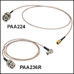

- SMB Female to BNC Male Connector
- Straight SMB: 12", 24", 48", or 72" Long Cable
- 90º SMB: 12", 24", 36", 48", or 72" Long Cable
- 50 Ω Impedance
- DC to 3.0 GHz Frequency Range
- 1000 V (RMS) Dielectric Withstanding Voltage
- 0.40" (10.2 mm) Minimum Bend Radius
- No Bare Brass, Suitable for Use in Laser Systems
These SMB female to BNC male cables are available with either a straight or 90º SMB connector. These cables can be used to connect our Polaris piezo actuators to our MDT693B or MDT694B piezo controllers. The BNC and right-angle SMB connectors are made of nickel-plated brass, while the straight SMB connectors are made of gold-plated brass. The RG-178 coaxial cable is flexible enough to reach a minimum bend radius of 0.40", and the 90° SMB connector (Item #s PAA2xxR) allows the cable to be connected in tight areas without putting lateral force on the connection, making this cable ideal for use in space-constrained setups.
Part Number | Description | Price | Availability |
|---|---|---|---|
PAA212 | SMB Coaxial Cable, Straight SMB Female to BNC Male, 12" (305 mm) | $16.05 | Today |
PAA224 | SMB Coaxial Cable, Straight SMB Female to BNC Male, 24" (609 mm) | $17.12 | Today |
PAA248 | SMB Coaxial Cable, Straight SMB Female to BNC Male, 48" (1219 mm) | $22.47 | Today |
PAA272 | SMB Coaxial Cable, Straight SMB Female to BNC Male, 72" (1829 mm) | $23.54 | Today |
PAA212R | SMB Coaxial Cable, 90° SMB Female to BNC Male, 12" (305 mm) | $16.05 | Today |
PAA224R | SMB Coaxial Cable, 90° SMB Female to BNC Male, 24" (609 mm) | $17.12 | Today |
PAA236R | SMB Coaxial Cable, 90° SMB Female to BNC Male, 36" (914 mm) | $24.93 | Today |
PAA248R | SMB Coaxial Cable, 90° SMB Female to BNC Male, 48" (1219 mm) | $28.89 | Today |
PAA272R | SMB Coaxial Cable, 90° SMB Female to BNC Male, 72" (1829 mm) | $31.03 | Today |
SMB-to-SMC Cables
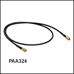

- Available in 12", 24", 48", or 72" Lengths
- 50 Ω Impedance
- DC - 1 GHz Frequency Range
- 500 VDC Dielectric Withstanding Voltage
- RG-174 Tubing with 0.40" (10.2 mm) Minimum Bend Radius
- Ø0.11" (Ø2.8 mm) Cable Diameter
These cables have a straight, SMB female connector on one end and a straight, SMC female connector on the other. These cables can be used to connect our Polaris piezo actuators to our K-Cube®, benchtop, or modular piezo controllers. The connectors are made of gold-plated brass. The RG-174 coaxial cable is flexible enough to reach a minimum bend radius of 0.40".
Part Number | Description | Price | Availability |
|---|---|---|---|
PAA312 | RG-174 Cable, Straight SMB Female to SMC Female, 12" (305 mm) | $14.98 | Today |
PAA324 | RG-174 Cable, Straight SMB Female to SMC Female, 24" (609 mm) | $16.05 | Today |
PAA348 | RG-174 Cable, Straight SMB Female to SMC Female, 48" (1219 mm) | $17.12 | Today |
PAA372 | RG-174 Cable, Straight SMB Female to SMC Female, 72" (1829 mm) | $18.19 | Today |
Torque Wrench for Polaris® Mount Lock Nuts


Click for Details
Figure G8.2 TW12 Torque Wrench Used to Secure the Lock Nut on POLARIS-K1S2P Mirror Mount

Click to Enlarge
Figure G8.1 Each wrench is engraved with its preset torque value and Item #.
- Preset 32 oz-in Wrench for Items Using the POLARIS-P20 Actuator
- Break-Over Design Ensures Proper Torque is Applied
- Ideal for Applications Requiring Long-Term Locking
- Hex Size: 12 mm
This torque wrench has a preset torque value to secure the lock nuts on Polaris mounts using the POLARIS-P20 actuator for long-term locking; see Table G8.3 for specifications. When the preset torque value has been achieved, the break-over design will cause the pivoting joint to "break," as shown in Figure G8.2. The wrench's hex head will move back into place once the force is removed. This design prevents further force from being applied to the lock nut. Engraved guidelines indicate the angle the wrench should pivot in order to apply the specified torque; pivoting the handle past these guidelines will over-torque the lock nut. Each wrench is also engraved with its preset torque value, torque direction, wrench size, and Item # for easy identification in the field.
This wrench is designed to be compatible with cleanroom and vacuum chamber applications. It is chemically cleaned using the Carpenter AAA passivation method to remove sulfur, iron, and contaminants from the surface. After passivation, it is assembled in a clean environment and double vacuum bagged to eliminate contamination when transported into a cleanroom. Finally, it is bead blasted to minimize reflections when working with setups that include lasers.
Please note that this wrench is not intended for use in applications where adjusters are frequently tuned, as these applications typically require torque values of 4 to 8 oz-in (0.03 to 0.06 N·m).
| Table G8.3 Specifications | ||||
|---|---|---|---|---|
| Item # | Torque | Torque Accuracy | Hex | Compatible Items |
| TW12 | 32 oz-in (0.23 N•m) | ±1.92 oz-in (0.014 N•m) | 12 mm | Stainless Steel Lock Nut for POLARIS-P20 Actuator |
Part Number | Description | Price | Availability |
|---|---|---|---|
TW12 | 12 mm Preset Torque Wrench for Polaris Lock Nuts, 32 oz-in | $138.27 | Today |