

Small Beam Diameter Scanning Galvo Mirror Systems

- For Small (<5 mm) Beam Diameters
- Single- and Dual-Axis Options with Choice of Mirror Coating
- Mounting Adapters for Easy Integration into Standard Thorlabs Optomechanics
GVS002
Dual-Axis Motor/Mirror Assembly with Silver Mirrors
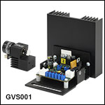
GVS001
Galvo Scanning System
Mounting Adapters are Available that Allow Our Single- and Dual-Axis Galvo Mirror Systems to be Integrated with Thorlabs' Standard Optomechanics
OVERVIEW
| Key Specificationsa | ||||
|---|---|---|---|---|
| Max Beam Diameter | 5 mm | |||
| 2-Axis System Beam Offset | 10 mm | |||
| Wavelength Range (Ravg > 95%) |
GVS00x (Silver): 500 nm - 2.0 µm GVS10x (Gold): 800 nm - 20.0 µm GVS20x (-E02): 400 nm - 750 nm |
|||
| Repeatability | 15 μrad | |||
| Damage Threshold GVS00x (Silver) GVS10x (Gold) GVS20x (-E02) |
3 J/cm2 at 1064 nm, 10 ns pulse 2 J/cm2 at 1064 nm, 10 ns pulse 0.25 J/cm2 at 532 nm, 10 ns pulse |
|||
| Linearity | 99.9% | |||
| Max Scan Angle (Mechanical Angle) |
±12.5° (w/ 0.8 V/deg scaling) |
|||
| Resolution (Mechanical) | With GPS011-xx Linear PSU: 0.0008° (15 µrad) With Standard Switch Mode PSU: 0.004° (70 µrad) |
|||
| Full Scale Bandwidth | DC to 100 Hz Square wave, DC to 250 Hz Sine wave, DC to 175 Hz Triangular Wave, DC to 175 Hz Sawtooth |
|||
| Small Angle (±0.2°) Bandwidth | DC to 1 kHz | |||
| Small Angle Step Responseb | 300 µs | |||
| Optical Position Sensor Output | 40 to 80 µA | |||
| Power Supply Requirements | ±15 to ±18 VDC | |||
Demo Units Available
Interested in trying a Small Beam Diameter Galvanometer System for your application? Contact us at techsales@thorlabs.com to request a demo unit.Features
- Single- and Dual-Axis Systems
- Moving Magnet Motor Design for Faster Response
- High-Precision Optical Mirror Position Detection
- Analog PD Control Electronics with Current Damping and Error Limiter
- Choice of Mirror Coatings:
- Protected Silver: 500 nm to 2.0 µm
- Protected Gold: 800 nm to 20.0 µm
- Broadband Dielectric: 400 nm to 750 nm
- Kits with Power Supply, Cables, and Driver Card Cover Available
- Mounting Adapters for Post and 30 mm Cage System Compatibility
- Tip and Tilt Platform Adapter Facilitates Attachment to Thorlabs' PY003
These high-speed Scanning Galvanometer Mirror Positioning Systems are designed for integration into OEM or custom laser beam steering applications that utilize laser beams smaller than 5 mm in diameter. Each system includes a single- or dual-axis galvo motor and mirror assembly, associated driver card(s), and driver card heatsink(s). A low noise, linear power supply unit (Item # prefix GPS011) and motor/mirror assembly heatsink (GHS003) are available separately. Upon initial setup of the system, a function generator or DAQ card will be needed for operating the servo drivers; see Chapters 3 and 4 in the manual for additional information.
Each galvo system includes a motor drive cable, which connects the driver board to the motor. This 1 m long cable is specially calibrated to both the driver board and the motor's internal sensor. We do not recommend installing and calibrating your own cable; please contact Tech Sales if your application requires a custom galvo system.
A range of mounting adapters is available to ease the integration of the single- and dual-axis galvo systems into optical systems. These include a 30 mm cage mount for a single-axis galvo mirror, a post and cage compatible mount for a dual-axis galvo mirror system, and adapter for the PY003 tip and tilt platform that is compatible with both single- and dual-axis galvo systems. An optional enclosure for the galvo driver card is also available.

Galvo Motor/Mirror Assembly
The galvo consists of a galvanometer-based scanning motor with an optical mirror mounted on the shaft and a detector that provides positional feedback to the control board. The moving magnet design for the GVS series of galvanometer motors was chosen over a stationary magnet and rotating coil design in order to provide the fastest response times and the highest system resonant frequency. The position of the mirror is encoded using an optical sensing system located inside of the motor housing.
Due to the large angular acceleration of the rotation shaft, the size, shape and inertia of the mirrors become significant factors in the design of high performance galvo systems. Furthermore, the mirror must remain rigid (flat) even when subjected to large accelerations. All these factors have been precisely balanced in our galvo systems in order to match the characteristics of the galvo motor and maximize performance of the system.
The mirrors are available from stock with silver, gold, or broadband coatings.

Scanning Galvo Mirror Assembly and Driver Board
All Thorlabs scanning galvo mirror systems feature a mounted single or dual axis mirror/motor assembly and driver card(s). Shown to the right is the GVS001 1D galvo mirror and driver card with heatsink. The mirror assembly feature multiple mounting holes and a rotatable collar mount for the mirror/motor. These small 5 mm galvo mirrors feature a plug style connector to the mirror assembly. Please see below for additional mounting options and accessories.
Servo Driver Board (All Systems)
The Proportional Derivative (PD) servo driver circuit interprets the signals from the optical position detecting system inside the motor and then produces the drive voltage required to rotate the mirror to the desired position. The scanner uses a non-integrating, Class 0 servo that is ideal for use in applications that require vector positioning (e.g., laser marking), raster positioning (printing or scanning laser microscopy), and some step-and-hold applications. Furthermore, the proportional derivative controller gives excellent dynamic performance. The circuit includes an additional current term to ensure stability at high accelerations. The same driver board is used in all our galvo systems.
System Operation
The servo driver must be connected to a DC power supply, the galvo motor, and an input voltage source (the monitoring connection is optional). For continuous scanning applications, a function generator with a square or sine wave output is sufficient for scanning the galvo mirror over its entire range. For more complex scanning patterns, a programmable voltage source such as a DAQ card can be used. Please note that these systems do not include a function generator or a DAQ card. The ratio between the input voltage and mirror position is switchable, either 0.5, 0.8 or 1. When set to 0.8, the ±10 V input will rotate the mirror over its full range of ±12.5°. The control circuit also provides monitoring outputs that allow the user to track the position of the mirror. In addition, voltages proportional to the drive current being supplied to the motor and the difference between the command position and the actual position of the mirror are supplied by the control circuit.
Closed-Loop Mirror Positioning
The angular orientation (position) of the mirror is optically encoded using an array of photocells and a light source, both of which are integrated into the interior of the galvanometer housing. Each mirror orientation corresponds to a unique ratio of signals from the photodiodes, which allows for the closed-loop operation of the galvo mirror system.
The systems can be driven to scan their full mechanical range of ±12.5° at a frequency of 100 Hz when using a square wave control input voltage or at 250 Hz when using a sine wave. For a single small-angle step of 0.2°, it takes the mirror 300 μs to come to rest at the command position. The scan frequency range is DC to 1 kHz and the angular resolution is 0.0008° (15 μrad).
SPECS
Galvanometer System Specifications
| Item # | GVS001 and GVS002 | GVS101 and GVS102 | GVS201 and GVS202 | |
|---|---|---|---|---|
| Mirror | ||||
| Maximum Beam Diameter | 5 mm | |||
| 2-Axis System Beam Offset | 10 mm | |||
| Material | Quartz | |||
| Coating | Protected Silver | Protected Gold | Broadband Dielectric (-E02) | |
| Wavelength Range | 500 nm to 2.0 µm | 800 nm to 20.0 µm | 400 nm to 750 nm | |
| Damage Thresholda | 3.0 J/cm2 | 2.0 J/cm2 | 0.25 J/cm2 | |
| Parallelism | <3 arcmin | |||
| Surface Quality | 40-20 Scratch-Dig | |||
| Front Surface Flatness (@633 nm) | λ | |||
| Clear Aperture | >90% of Dimension | |||
| Motor and Position Sensor | ||||
| Linearity | 99.9% | |||
| Scale Drift | 40 ppm/°C (Max) | |||
| Zero Drift | 10 μrad/°C (Max) | |||
| Repeatability | 15 μrad | |||
| Resolution (Mechanical) | With GPS011-xx Linear PSU: 0.0008° (15 µrad) With Standard Switch Mode PSU: 0.004° (70 µrad) |
|||
| Average Current | 1 A | |||
| Peak Current | 5 A | |||
| Maximum Scan Angle (Mechanical Angle) |
±12.5° (Input Scale Factor 0.8 V per degree) | |||
| Motor Weight (With Cables, Without Brackets) |
50 g | |||
| Operating Temperature Range | 0 to 40 °C | |||
| Optical Position Sensor Output Range | 40 to 80 µA | |||
| Drive Electronics | ||||
| Full Scale Bandwidth | DC to 100 Hz Square Wave, DC to 250 Hz Sine Wave, DC to 175 Hz Triangular Wave, DC to 175 Hz Sawtooth |
|||
| Small Angle (±0.2°) Bandwidth | DC to 1 kHz | |||
| Small Angle Step Responseb | 300 µs | |||
| Power Supply | ±15 to ±18 VDC (1.25 A rms, 5 A peak Max) |
|||
| Analog Signal Input Resistance | 20 kΩ ± 1% (Differential Input) | |||
| Position Signal Output Resistance | 1 kΩ ± 1% | |||
| Analog Position Signal Input Range | ±10 V | |||
| Mechanical Position Signal Input Scale Factor | Switchable: 1.0 V, 0.8 V or 0.5 V per degree | |||
| Mechanical Position Signal Output Scale Factor | 0.5 V per degree | |||
| Operating Temperature Range | 0 to 40 °C | |||
| Servo Board Size (W x D x H) | 85 mm x 74 mm x 44 mm (3.35" x 2.9" x 1.73") | |||
Power Supply Specifications
| Item # | GPS011-US | GPS011-EC | GPS011-JP |
|---|---|---|---|
| Input Voltage | 115 VAC, 60 Hz | 230 VAC, 50 Hz | 100 VAC, 50/60 Hz |
| Output Voltage | ±15 VDC, 3.0 A / 0.1 A, 1.4/6.3 ms | ||
| Fuses | T2.0 A Anti-Surge Ceramic | T1.0 A Anti-Surge Ceramic | T2.5 A Anti-Surge Ceramic |
| Dimensions | 179 mm x 274 mm (Max) x 122 mm (7.05" x 10.79" (Max) x 4.8") |
||
| Weight | 4.73 kg (10.4 lbs) | ||
PIN DIAGRAMS
When configuring and operating the galvo scanning system, use only the cables supplied. Do not extend the cables.The driver boards and motors are calibrated with these cables. Using different cables will affect the performance of the system. Custom longer cables are available, but the units will require re-calibration if these are not specified at time of order. Contact Tech Support for more details.
GVS Series Driver Connections

Click to Enlarge
Overview of PCB Connectors. Details on each connector can be found below.
J10 Power Connector
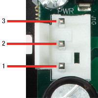
| Pin | Designation |
|---|---|
| 1 | + 15 V |
| 2 | Ground |
| 3 | - 15 V |
J6 Diagnostics Connector
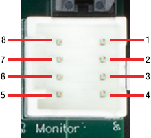
| Pin | Designation |
|---|---|
| 1 | Scanner Position |
| 2 | Internal Command Signal |
| 3 | Positioning Error x 5 |
| 4 | Motor Drive Current |
| 5 | Not Connected |
| 6 | Test Input (NC) |
| 7 | Motor + Coil Voltage / 2 |
| 8 | Ground |
J9 Motor Connector
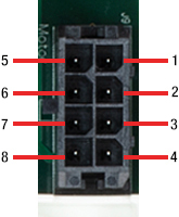
| Pin | Designation |
|---|---|
| 1 | Position Sensor A Current |
| 2 | Position Sensor Ground |
| 3 | Position Sensor Cable Shield |
| 4 | Drive Cable Shield |
| 5 | Position Sensor B Current |
| 6 | Position Sensor Power |
| 7 | Motor + Coil |
| 8 | Motor - Coil |
Galvo Assembly Motor Connector
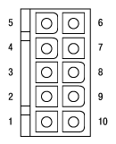
| Pin | Designation |
|---|---|
| 1 | Motor + Coil (Power Shield Floating) |
| 2 | Motor - Coil (Power Shield Floating) |
| 3 | Not Used |
| 4 | Not Used |
| 5 | Position Sensor B Current |
| 6 | Position Sensor Ground |
| 7 | Position Sensor A Current |
| 8 | Position Sensor Power (Automated Gain Control) |
| 9 | Position Sensor Cable Shield |
| 10 | Not Used |
J7 Command Input Connector
| Pin | Designation |
|---|---|
| 1 | Command Input +ve |
| 2 | Command Input -ve |
| 3 | DRV OK |
| 4 | External Enable |
| 5 | -12 V Output (Low Impedance O/P) |
| 6 | +12 V Output (Low Impedance O/P) |
| 7 | Ground |
| 8 | Ground |
JP7 Volts/Degree Scaling Factor Control
with the scaling set to 1.0 V/°, where the max scan angle is 10°, and is compatible with driver cards manufactured before October 2009.
To set the maximum scan angle to ±12.5°, set the scaling factor to 0.8 V/° by placing a jumper across the pins as shown above. Similarly, the 0.5 V/° scaling
factor is provided to allow the full scan angle to be achieved using small input signals. In this case, the input voltage should be limited to ±6.25 V max.
External Enabling of the Driver Board
The drive electronics can be configured for external enabling by placing a jumper across pins 2 and 3 of JP4.

JP4
Once this has been done, the user can enable or disable the drive electronics by applying a 5 V CMOS signal to
J7 pin 4.
If a logic high or no signal is applied, the drive electronics will be enabled. If a logic low signal is applied, then the driver will be disabled.
| Pin | Designation |
|---|---|
| 1 | Command Input +ve |
| 2 | Command Input -ve |
| 3 | No Connect |
| 4 | External Enable |
| 5 | -12 V Output |
| 6 | +12 V Output |
| 7 | Ground |
| 8 | Ground |
J7
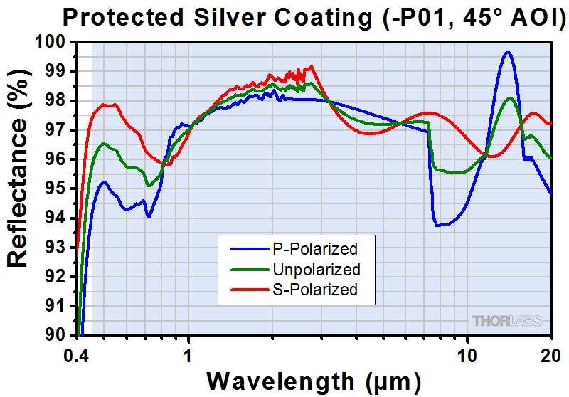
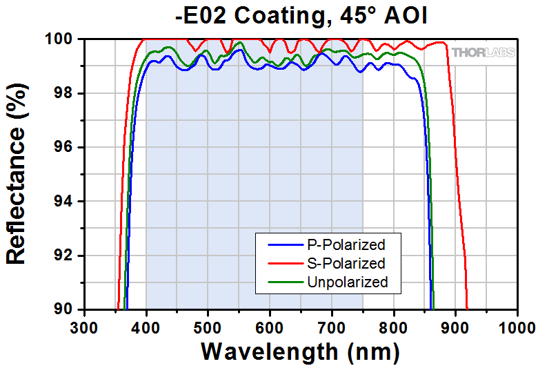
GRAPHS
The curves below show the reflection data for the coated mirrors supplied with the GVS series galvo systems. The shaded regions denote the ranges over which we recommend using the respective coating. Please note that the reflectance outside of these bands is not as rigorously monitored in quality control, and can vary from lot to lot, especially in out-of-band regions where the reflectance is fluctuating or sloped.

DAMAGE THRESHOLDS
| Damage Threshold Specifications | |
|---|---|
| Item # Prefix | Damage Threshold |
| GVS00- | 3 J/cm2 at 1064 nm, 10 ns |
| GVS10- | 2 J/cm2 at 1064 nm, 10 ns |
| GVS20- | 0.25 J/cm2 at 532 nm, 10 ns |
Damage Threshold Data for Thorlabs' Small Beam Diameter Scanning Galvo Mirror Systems
The specifications to the right are measured data for Thorlabs' small beam diameter scanning galvo mirror systems. Damage threshold specifications are constant for a given item number prefix, regardless of the number of drivers or measuring system.
Laser Induced Damage Threshold Tutorial
The following is a general overview of how laser induced damage thresholds are measured and how the values may be utilized in determining the appropriateness of an optic for a given application. When choosing optics, it is important to understand the Laser Induced Damage Threshold (LIDT) of the optics being used. The LIDT for an optic greatly depends on the type of laser you are using. Continuous wave (CW) lasers typically cause damage from thermal effects (absorption either in the coating or in the substrate). Pulsed lasers, on the other hand, often strip electrons from the lattice structure of an optic before causing thermal damage. Note that the guideline presented here assumes room temperature operation and optics in new condition (i.e., within scratch-dig spec, surface free of contamination, etc.). Because dust or other particles on the surface of an optic can cause damage at lower thresholds, we recommend keeping surfaces clean and free of debris. For more information on cleaning optics, please see our Optics Cleaning tutorial.
Testing Method
Thorlabs' LIDT testing is done in compliance with ISO/DIS 11254 and ISO 21254 specifications.
First, a low-power/energy beam is directed to the optic under test. The optic is exposed in 10 locations to this laser beam for 30 seconds (CW) or for a number of pulses (pulse repetition frequency specified). After exposure, the optic is examined by a microscope (~100X magnification) for any visible damage. The number of locations that are damaged at a particular power/energy level is recorded. Next, the power/energy is either increased or decreased and the optic is exposed at 10 new locations. This process is repeated until damage is observed. The damage threshold is then assigned to be the highest power/energy that the optic can withstand without causing damage. A histogram such as that below represents the testing of one BB1-E02 mirror.
The photograph above is a protected aluminum-coated mirror after LIDT testing. In this particular test, it handled 0.43 J/cm2 (1064 nm, 10 ns pulse, 10 Hz, Ø1.000 mm) before damage.
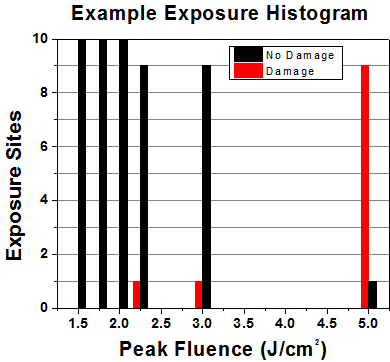
| Example Test Data | |||
|---|---|---|---|
| Fluence | # of Tested Locations | Locations with Damage | Locations Without Damage |
| 1.50 J/cm2 | 10 | 0 | 10 |
| 1.75 J/cm2 | 10 | 0 | 10 |
| 2.00 J/cm2 | 10 | 0 | 10 |
| 2.25 J/cm2 | 10 | 1 | 9 |
| 3.00 J/cm2 | 10 | 1 | 9 |
| 5.00 J/cm2 | 10 | 9 | 1 |
According to the test, the damage threshold of the mirror was 2.00 J/cm2 (532 nm, 10 ns pulse, 10 Hz, Ø0.803 mm). Please keep in mind that these tests are performed on clean optics, as dirt and contamination can significantly lower the damage threshold of a component. While the test results are only representative of one coating run, Thorlabs specifies damage threshold values that account for coating variances.
Continuous Wave and Long-Pulse Lasers
When an optic is damaged by a continuous wave (CW) laser, it is usually due to the melting of the surface as a result of absorbing the laser's energy or damage to the optical coating (antireflection) [1]. Pulsed lasers with pulse lengths longer than 1 µs can be treated as CW lasers for LIDT discussions.
When pulse lengths are between 1 ns and 1 µs, laser-induced damage can occur either because of absorption or a dielectric breakdown (therefore, a user must check both CW and pulsed LIDT). Absorption is either due to an intrinsic property of the optic or due to surface irregularities; thus LIDT values are only valid for optics meeting or exceeding the surface quality specifications given by a manufacturer. While many optics can handle high power CW lasers, cemented (e.g., achromatic doublets) or highly absorptive (e.g., ND filters) optics tend to have lower CW damage thresholds. These lower thresholds are due to absorption or scattering in the cement or metal coating.
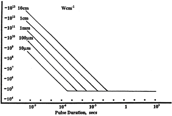
LIDT in linear power density vs. pulse length and spot size. For long pulses to CW, linear power density becomes a constant with spot size. This graph was obtained from [1].
Pulsed lasers with high pulse repetition frequencies (PRF) may behave similarly to CW beams. Unfortunately, this is highly dependent on factors such as absorption and thermal diffusivity, so there is no reliable method for determining when a high PRF laser will damage an optic due to thermal effects. For beams with a high PRF both the average and peak powers must be compared to the equivalent CW power. Additionally, for highly transparent materials, there is little to no drop in the LIDT with increasing PRF.
In order to use the specified CW damage threshold of an optic, it is necessary to know the following:
- Wavelength of your laser
- Beam diameter of your beam (1/e2)
- Approximate intensity profile of your beam (e.g., Gaussian)
- Linear power density of your beam (total power divided by 1/e2 beam diameter)
Thorlabs expresses LIDT for CW lasers as a linear power density measured in W/cm. In this regime, the LIDT given as a linear power density can be applied to any beam diameter; one does not need to compute an adjusted LIDT to adjust for changes in spot size, as demonstrated by the graph to the right. Average linear power density can be calculated using the equation below.

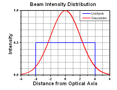
The calculation above assumes a uniform beam intensity profile. You must now consider hotspots in the beam or other non-uniform intensity profiles and roughly calculate a maximum power density. For reference, a Gaussian beam typically has a maximum power density that is twice that of the uniform beam (see lower right).
Now compare the maximum power density to that which is specified as the LIDT for the optic. If the optic was tested at a wavelength other than your operating wavelength, the damage threshold must be scaled appropriately. A good rule of thumb is that the damage threshold has a linear relationship with wavelength such that as you move to shorter wavelengths, the damage threshold decreases (i.e., a LIDT of 10 W/cm at 1310 nm scales to 5 W/cm at 655 nm):
While this rule of thumb provides a general trend, it is not a quantitative analysis of LIDT vs wavelength. In CW applications, for instance, damage scales more strongly with absorption in the coating and substrate, which does not necessarily scale well with wavelength. While the above procedure provides a good rule of thumb for LIDT values, please contact Tech Support if your wavelength is different from the specified LIDT wavelength. If your power density is less than the adjusted LIDT of the optic, then the optic should work for your application.
Please note that we have a buffer built in between the specified damage thresholds online and the tests which we have done, which accommodates variation between batches. Upon request, we can provide individual test information and a testing certificate. The damage analysis will be carried out on a similar optic (customer's optic will not be damaged). Testing may result in additional costs or lead times. Contact Tech Support for more information.
Pulsed Lasers
As previously stated, pulsed lasers typically induce a different type of damage to the optic than CW lasers. Pulsed lasers often do not heat the optic enough to damage it; instead, pulsed lasers produce strong electric fields capable of inducing dielectric breakdown in the material. Unfortunately, it can be very difficult to compare the LIDT specification of an optic to your laser. There are multiple regimes in which a pulsed laser can damage an optic and this is based on the laser's pulse length. The highlighted columns in the table below outline the relevant pulse lengths for our specified LIDT values.
Pulses shorter than 10-9 s cannot be compared to our specified LIDT values with much reliability. In this ultra-short-pulse regime various mechanics, such as multiphoton-avalanche ionization, take over as the predominate damage mechanism [2]. In contrast, pulses between 10-7 s and 10-4 s may cause damage to an optic either because of dielectric breakdown or thermal effects. This means that both CW and pulsed damage thresholds must be compared to the laser beam to determine whether the optic is suitable for your application.
| Pulse Duration | t < 10-9 s | 10-9 < t < 10-7 s | 10-7 < t < 10-4 s | t > 10-4 s |
|---|---|---|---|---|
| Damage Mechanism | Avalanche Ionization | Dielectric Breakdown | Dielectric Breakdown or Thermal | Thermal |
| Relevant Damage Specification | No Comparison (See Above) | Pulsed | Pulsed and CW | CW |
When comparing an LIDT specified for a pulsed laser to your laser, it is essential to know the following:
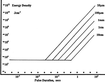
LIDT in energy density vs. pulse length and spot size. For short pulses, energy density becomes a constant with spot size. This graph was obtained from [1].
- Wavelength of your laser
- Energy density of your beam (total energy divided by 1/e2 area)
- Pulse length of your laser
- Pulse repetition frequency (prf) of your laser
- Beam diameter of your laser (1/e2 )
- Approximate intensity profile of your beam (e.g., Gaussian)
The energy density of your beam should be calculated in terms of J/cm2. The graph to the right shows why expressing the LIDT as an energy density provides the best metric for short pulse sources. In this regime, the LIDT given as an energy density can be applied to any beam diameter; one does not need to compute an adjusted LIDT to adjust for changes in spot size. This calculation assumes a uniform beam intensity profile. You must now adjust this energy density to account for hotspots or other nonuniform intensity profiles and roughly calculate a maximum energy density. For reference a Gaussian beam typically has a maximum energy density that is twice that of the 1/e2 beam.
Now compare the maximum energy density to that which is specified as the LIDT for the optic. If the optic was tested at a wavelength other than your operating wavelength, the damage threshold must be scaled appropriately [3]. A good rule of thumb is that the damage threshold has an inverse square root relationship with wavelength such that as you move to shorter wavelengths, the damage threshold decreases (i.e., a LIDT of 1 J/cm2 at 1064 nm scales to 0.7 J/cm2 at 532 nm):
You now have a wavelength-adjusted energy density, which you will use in the following step.
Beam diameter is also important to know when comparing damage thresholds. While the LIDT, when expressed in units of J/cm², scales independently of spot size; large beam sizes are more likely to illuminate a larger number of defects which can lead to greater variances in the LIDT [4]. For data presented here, a <1 mm beam size was used to measure the LIDT. For beams sizes greater than 5 mm, the LIDT (J/cm2) will not scale independently of beam diameter due to the larger size beam exposing more defects.
The pulse length must now be compensated for. The longer the pulse duration, the more energy the optic can handle. For pulse widths between 1 - 100 ns, an approximation is as follows:
Use this formula to calculate the Adjusted LIDT for an optic based on your pulse length. If your maximum energy density is less than this adjusted LIDT maximum energy density, then the optic should be suitable for your application. Keep in mind that this calculation is only used for pulses between 10-9 s and 10-7 s. For pulses between 10-7 s and 10-4 s, the CW LIDT must also be checked before deeming the optic appropriate for your application.
Please note that we have a buffer built in between the specified damage thresholds online and the tests which we have done, which accommodates variation between batches. Upon request, we can provide individual test information and a testing certificate. Contact Tech Support for more information.
[1] R. M. Wood, Optics and Laser Tech. 29, 517 (1998).
[2] Roger M. Wood, Laser-Induced Damage of Optical Materials (Institute of Physics Publishing, Philadelphia, PA, 2003).
[3] C. W. Carr et al., Phys. Rev. Lett. 91, 127402 (2003).
[4] N. Bloembergen, Appl. Opt. 12, 661 (1973).
LIDT CALCULATIONS

In order to illustrate the process of determining whether a given laser system will damage an optic, a number of example calculations of laser induced damage threshold are given below. For assistance with performing similar calculations, we provide a spreadsheet calculator that can be downloaded by clicking the button to the right. To use the calculator, enter the specified LIDT value of the optic under consideration and the relevant parameters of your laser system in the green boxes. The spreadsheet will then calculate a linear power density for CW and pulsed systems, as well as an energy density value for pulsed systems. These values are used to calculate adjusted, scaled LIDT values for the optics based on accepted scaling laws. This calculator assumes a Gaussian beam profile, so a correction factor must be introduced for other beam shapes (uniform, etc.). The LIDT scaling laws are determined from empirical relationships; their accuracy is not guaranteed. Remember that absorption by optics or coatings can significantly reduce LIDT in some spectral regions. These LIDT values are not valid for ultrashort pulses less than one nanosecond in duration.
A Gaussian beam profile has about twice the maximum intensity of a uniform beam profile.
CW Laser Example
Suppose that a CW laser system at 1319 nm produces a 0.5 W Gaussian beam that has a 1/e2 diameter of 10 mm. A naive calculation of the average linear power density of this beam would yield a value of 0.5 W/cm, given by the total power divided by the beam diameter:
However, the maximum power density of a Gaussian beam is about twice the maximum power density of a uniform beam, as shown in the graph to the right. Therefore, a more accurate determination of the maximum linear power density of the system is 1 W/cm.
An AC127-030-C achromatic doublet lens has a specified CW LIDT of 350 W/cm, as tested at 1550 nm. CW damage threshold values typically scale directly with the wavelength of the laser source, so this yields an adjusted LIDT value:
The adjusted LIDT value of 350 W/cm x (1319 nm / 1550 nm) = 298 W/cm is significantly higher than the calculated maximum linear power density of the laser system, so it would be safe to use this doublet lens for this application.
Pulsed Nanosecond Laser Example: Scaling for Different Pulse Durations
Suppose that a pulsed Nd:YAG laser system is frequency tripled to produce a 10 Hz output, consisting of 2 ns output pulses at 355 nm, each with 1 J of energy, in a Gaussian beam with a 1.9 cm beam diameter (1/e2). The average energy density of each pulse is found by dividing the pulse energy by the beam area:
As described above, the maximum energy density of a Gaussian beam is about twice the average energy density. So, the maximum energy density of this beam is ~0.7 J/cm2.
The energy density of the beam can be compared to the LIDT values of 1 J/cm2 and 3.5 J/cm2 for a BB1-E01 broadband dielectric mirror and an NB1-K08 Nd:YAG laser line mirror, respectively. Both of these LIDT values, while measured at 355 nm, were determined with a 10 ns pulsed laser at 10 Hz. Therefore, an adjustment must be applied for the shorter pulse duration of the system under consideration. As described on the previous tab, LIDT values in the nanosecond pulse regime scale with the square root of the laser pulse duration:
This adjustment factor results in LIDT values of 0.45 J/cm2 for the BB1-E01 broadband mirror and 1.6 J/cm2 for the Nd:YAG laser line mirror, which are to be compared with the 0.7 J/cm2 maximum energy density of the beam. While the broadband mirror would likely be damaged by the laser, the more specialized laser line mirror is appropriate for use with this system.
Pulsed Nanosecond Laser Example: Scaling for Different Wavelengths
Suppose that a pulsed laser system emits 10 ns pulses at 2.5 Hz, each with 100 mJ of energy at 1064 nm in a 16 mm diameter beam (1/e2) that must be attenuated with a neutral density filter. For a Gaussian output, these specifications result in a maximum energy density of 0.1 J/cm2. The damage threshold of an NDUV10A Ø25 mm, OD 1.0, reflective neutral density filter is 0.05 J/cm2 for 10 ns pulses at 355 nm, while the damage threshold of the similar NE10A absorptive filter is 10 J/cm2 for 10 ns pulses at 532 nm. As described on the previous tab, the LIDT value of an optic scales with the square root of the wavelength in the nanosecond pulse regime:
This scaling gives adjusted LIDT values of 0.08 J/cm2 for the reflective filter and 14 J/cm2 for the absorptive filter. In this case, the absorptive filter is the best choice in order to avoid optical damage.
Pulsed Microsecond Laser Example
Consider a laser system that produces 1 µs pulses, each containing 150 µJ of energy at a repetition rate of 50 kHz, resulting in a relatively high duty cycle of 5%. This system falls somewhere between the regimes of CW and pulsed laser induced damage, and could potentially damage an optic by mechanisms associated with either regime. As a result, both CW and pulsed LIDT values must be compared to the properties of the laser system to ensure safe operation.
If this relatively long-pulse laser emits a Gaussian 12.7 mm diameter beam (1/e2) at 980 nm, then the resulting output has a linear power density of 5.9 W/cm and an energy density of 1.2 x 10⁻⁴ J/cm2 per pulse. This can be compared to the LIDT values for a WPQ10E-980 polymer zero-order quarter-wave plate, which are 5 W/cm for CW radiation at 810 nm and 5 J/cm2 for a 10 ns pulse at 810 nm. As before, the CW LIDT of the optic scales linearly with the laser wavelength, resulting in an adjusted CW value of 6 W/cm at 980 nm. On the other hand, the pulsed LIDT scales with the square root of the laser wavelength and the square root of the pulse duration, resulting in an adjusted value of 55 J/cm2 for a 1 µs pulse at 980 nm. The pulsed LIDT of the optic is significantly greater than the energy density of the laser pulse, so individual pulses will not damage the wave plate. However, the large average linear power density of the laser system may cause thermal damage to the optic, much like a high-power CW beam.
Small Beam Diameter Galvanometer Systems
- 1D and 2D Scanning Galvo Mirror Systems
- Silver, Gold, and Broadband (E02) Coating Options
- Includes 1 or 2 Driver Cards for Single or Dual Mirror Systems, Respectively
- Includes Driver Card Heat Sink(s)
- Power Supply Not Included
Thorlabs Scanning Galvo Mirror Systems are available in single and dual axis configurations for small (<5 mm) beam applications. A choice of mirror coatings is available as described above. Each 1D system includes one driver card, one driver card heat sink, and one single mirror system. Each 2D system includes two driver cards, two driver card heatsinks, and a dual mirror system. These galvo systems do not include a power supply, driver card cover, or galvo mirror heatsink, which are highly recommended for demanding applications where vigorous scanning and stability are required. These accessories are sold below and can be purchased separately.
Part Number | Description | Price | Availability |
|---|---|---|---|
GVS001 | 1D Galvo System, Silver-Coated Mirror, PSU Not Included | $1,148.66 | Today |
GVS101 | Customer Inspired! 1D Galvo System, Gold-Coated Mirror, PSU Not Included | $1,237.85 | Today |
GVS201 | Customer Inspired! 1D Galvo System, Broadband Mirror for 400-750 nm (-E02), PSU Not Included | $1,553.63 | Today |
GVS002 | 2D Galvo System, Silver-Coated Mirrors, PSU Not Included | $2,347.94 | 7-10 Days |
GVS102 | Customer Inspired! 2D Galvo System, Gold-Coated Mirrors, PSU Not Included | $2,347.94 | Today |
GVS202 | Customer Inspired! 2D Galvo System, Broadband Mirrors for 400-750 nm (-E02), PSU Not Included | $2,785.47 | Today |
Small Beam Diameter Galvo System Kits
| Kit Contentsa | |||
|---|---|---|---|
| Item # | Galvo System |
Power Supply |
Driver Card Cover(s) |
| GVSK1-US | GVS001 | GPS011-US | GCE001 |
| GVSK2-US | GVS002 | ||
| GVSK1-EC | GVS001 | GPS011-EC | |
| GVSK2-EC | GVS002 | ||
| GVSK1-JP | GVS001 | GPS011-JP | |
| GVSK2-JP | GVS002 | ||
- Each Kit Includes:
- GVS001 or GVS002 Galvo System
- Region-Specific Power Supply
- Driver Card Cover(s)
- All Necessary Cables
- Complete 1D or 2D Scanning 5 mm Galvo Mirror Systems
- Protected Silver Mirror Coating
- Optically Encoded Mirror Position
- 99.9% Motor and Position Sensor Linearity
- Advanced Analog Control Circuit (Servo Driver) with Current Damping and Error Limiter
The GVSK1 and GVSK2 Series Galvo Mirror System Kits include everything necessary for operating 1D or 2D scanning mirror systems for small diameter beams. These closed-loop systems are ideal for raster and vector scanning applications as well as some step-and-hold applications. The GVSK1 and GVSK2 series kits include the GVS001 and GVS002 silver-coated mirror systems, respectively, together with the GPS011-xx linear power supply and a GCE001 cover for the servo driver boards. The power supply can power two 1D scanning mirrors or one 2D scanning mirror assembly.
We highly recommend using the GHS003(/M) heatsink and post mounting adapter (sold separately below) to cool the galvo mirror for rapid scanning applications that necessitate additional heat dissipation.
Part Number | Description | Price | Availability |
|---|---|---|---|
GVSK1-EC | 1D Galvo System Kit, Silver-Coated Mirror, 230 VAC | $1,800.30 | Today |
GVSK2-EC | 2D Galvo System Kit, Silver-Coated Mirrors, 230 VAC | $3,068.16 | Today |
GVSK1-US | 1D Galvo System Kit, Silver-Coated Mirror, 115 VAC | $1,800.30 | Today |
GVSK2-US | 2D Galvo System Kit, Silver-Coated Mirrors, 115 VAC | $3,068.16 | Today |
GVSK1-JP | 1D Galvo System Kit, Silver-Coated Mirror, 100 VAC | $1,800.30 | 7-10 Days |
GVSK2-JP | 2D Galvo System Kit, Silver-Coated Mirrors, 100 VAC | $3,068.16 | 7-10 Days |
Galvo System Linear Power Supplies
- Compatible with Galvo Systems Above
- Low Noise, Linear Supply Minimizes Electrical Interference
- Capable of Powering Two Server Driver Cards Simultaneously
- Configured for Regional Voltage Requirements upon Shipping
These power supplies are low noise, linear supplies designed to minimize electrical interference for maximum system resolution. They deliver ±15 VDC at 3 A and are configured to accept a mains voltage of 115 VAC (for GPS011-US), 230 VAC (for GPS011-EC), or 100 VAC (for GPS011-JP). Each power supply is compatible with all of our galvo systems available above. Two 2 m (6.5') power cables are included.
As an alternative, a standard switching mode power supply may be used for low demand applications.
Part Number | Description | Price | Availability |
|---|---|---|---|
GPS011-EC | Customer Inspired! 1D or 2D Galvo System Linear Power Supply, 230 VAC | $582.95 | Today |
GPS011-US | Customer Inspired! 1D or 2D Galvo System Linear Power Supply, 115 VAC | $582.95 | Today |
GPS011-JP | Customer Inspired! 1D or 2D Galvo System Linear Power Supply, 100 VAC | $582.95 | 7-10 Days |
Galvo Driver Card Cover
Click to Enlarge
The GCE001 can be used to cover the Galvo Systems' servo driver boards.
The GCE001 is a convenient enclosure for servo driver cards. Simply bolt it onto the servo driver bracket using the M3 screws and hex key supplied.
Note: This item is not compatible with early models of the servo driver card. Contact Tech Support for more details.
Part Number | Description | Price | Availability |
|---|---|---|---|
GCE001 | Galvo Driver Card Cover | $69.00 | Today |
Galvo Mount Heatsink and Post Mounting Adapter
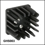

Click to Enlarge
2D Galvo System Mounted on Heatsink on a Ø1/2" Post
- Provides Additional Cooling to Prevent Thermal Cutout
- Attaches Directly to the 1D and 2D Mirror Mounts
- Convenient Post Adapter to Thorlabs’ 8-32 (M4) Threaded Posts
The GHS003 galvo mirror heatsink attaches directly to the single-axis and dual-axis mirror mounts to provide device cooling and alternate mounting options. Mounting screws are supplied with the unit.
Heat from the galvo mirrors is typically dissipated through the normal mounting options. However, applications involving rapidly changing drive signals can create excess heat buildup, causing the galvo motor to fail or driver board thermal cutout to trip. If the cutout occurs repeatedly, we recommend using the GHS003 Heatsink. The heatsink also serves as a post adapter, allowing the galvo mirror assembly to be mounted on our Ø1/2" 8-32 (M4) threaded posts.
Part Number | Description | Price | Availability |
|---|---|---|---|
GHS003/M | Galvo Heatsink and Post Mounting Adapter, Metric | $32.08 | Today |
GHS003 | Galvo Heatsink and Post Mounting Adapter, Imperial | $32.08 | Today |
30 mm Cage System Adapter for 1D Galvo Mirrors
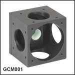

Click to Enlarge
Shown is a CM001 used to mount a GVS001 into a 30 mm cage system. Refer to the GCM001 manual for detailed instructions.
- Mount a 1D Galvo System into a 30 mm Cage System
- SM1-Threaded (1.035"-40) Port on Four Sides
- Four 4-40 Tapped Holes on Four Sides for Compatibility with Ø6 mm ER Series Cage Rods
- Bottom Face Features a Ø1.75" (44.5 mm) Through Hole for Additional Mounting Options
The GCM001 Cage System Adapter is used to mount the GVSX01 single-axis galvo systems into a 30 mm cage system. The adapter also features four SM1 threads and an open bottom for further mounting options.
Note: The input and output are on the same plane.
Part Number | Description | Price | Availability |
|---|---|---|---|
GCM001 | 1D Galvo 30 mm Cage System Mount | $165.43 | Today |
Mounting Adapter for Small Beam 2D Galvo Mirrors and Scan Lenses
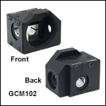

Click for Details
GCM102(/M) Mechanical Drawing

Click to Enlarge
Beam Path Shown Through the Input Port, Reflecting off Both Galvo Mirrors, and then Exiting Through the SM2-Threaded Output Port
- Mount a 2D Galvo System to a Post, 30 mm Cage System, or 66 mm Rail Carriage
- Internal SM05 (0.535"-40) and SM1 (1.035"-40) Threads on Input Port
- Internal SM2 (2.035"-40) Threads on Output Port
- Compatible with Thorlabs' Selection of Scan Lenses (See Compatibility Table Below)
Thorlabs' GCM102(/M) is designed to securely mount any dual-axis, small beam diameter galvo mirror system. Once installed in the mount, the galvo system can be attached to a post, 30 mm cage system, or 66 mm optical rail carriage, as shown in the images below.
The mount features an internally SM2-threaded (2.035"-40) output port that, when used with the proper adapter, allows any of our scan lenses to be attached at the proper scan distance from the galvo mirrors; see the compatibility table below for more details. The input port is both internally SM05- (0.535"-40) and SM1-threaded (1.035"-40) for direct compatibility with Ø1/2" and Ø1" lens tubes. Additionally, four 4-40 tapped holes centered around the input port provide compatibility with 30 mm cage systems. When each port is used in combination with our lens tubes, port plugs, and/or scan lenses, the system will be light tight. The input and output ports are centered around the X- and Y-axis galvo mirrors, respectively; please note that they are in different planes.
The bottom of the mount includes two 1/4"-20 (M6), three 8-32 (M4), and two 4-40 (M3) tapped mounting holes. Each mounting hole is aligned for compatibility with our C1511 (C1511/M) and C1545 (C1545/M) post clamp adapters; Ø1/2", Ø1", and Ø1.5" mounting posts; and XT66P2 (XT66P2/M) and XT66RC rail carriages, as shown in the images below. Please see section 3.3 of the manual for more details about the various mounting options available.
The X- and Y-axis galvo mirrors are mounted using the two through holes in the side and rear of the unit. A flexure clamp that is actuated using the included 5/64" (3 mm) hex key secures each galvo mirror in place. An SM05-threaded viewing port is provided above the mirrors to assist in installation, while two 1/4"-20 (M6) through tapped holes provide access to each flexure clamp. The SM05 port and 1/4"-20 (M6) through tapped holes, which are located on the top of the GCM102, are blocked using an SM05PL plug or a 1/4"-20 (M6) setscrew, respectively, so that the system can remain light tight. For step-by-step instructions on how to install the galvo mirror, please see section 3.1 of the manual.


| Scan Lens Compatibilitya | |||
|---|---|---|---|
| Item # | Scanning Distanceb | Lens Mounting Thread | Required Adapterb |
| LSM02(-BB) | 16.1 mm ± 5 mm | External M25 x 0.75 | GCMA1 |
| LSM54-850 |
17.8 mm ± 7.5 mm | SM2A33 | |
| LSM54-1050 |
|||
| LSM54-1310 | |||
| LSM03(-BB) | 18.9 mm ± 5 mm | GCMA1c | |
| LSM04(-BB) | |||
| LSM03-VIS | 29.0 mm ± 5 mm | SM2A33 and SM2L03 | |
| SL50-CLS2 | 37.8 ± 4 mm | External SM30 (M30.5 x 0.5) |
SM2A11 and SM2V05 |
| SL50-2P2 | |||
| LSM05(-BB) | 75.5 mm ± 5 mm | External SM2 (2.035"-40) | SM2L20 |
| CLS-SL | 58 ± 6 mm | SM2L05 and SM2V05 | |
Part Number | Description | Price | Availability |
|---|---|---|---|
GCM102/M | Customer Inspired! Mounting Adapter for a 2D Galvo System, Metric | $277.23 | Today |
GCM102 | Customer Inspired! Mounting Adapter for a 2D Galvo System, Imperial | $277.23 | 7-10 Days |
Tip and Tilt Platform Adapter
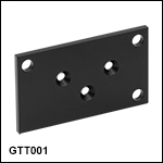
- Three Ø3.4 mm Countersunk Through Holes for Attachment to a 1D or 2D Galvo System
- Three Ø5.0 mm Through Holes for Attachment to the PY003 (PY003/M) Tip and Tilt Platform
The GTT001 Tip and Tilt Platform Adapter allows the GVSX01 and GVSX02 Galvo Systems to be mounted on a PY003 Tip and Tilt Platform. Included with the GTT001 are three M3 cap screws, three 8-32 cap screws, and three M3 countersunk screws for mounting purposes.
Part Number | Description | Price | Availability |
|---|---|---|---|
GTT001 | Galvo Mount Tip-Tilt Platform Adapter | $40.15 | Today |