FiberPort Collimators / Couplers

- Ultrastable Micropositioning Alignment with Five Degrees of Freedom Plus Rotation Adjustment
- Usable with Single Mode, Multimode, and Polarization-Maintaining Fiber
- Aspheric or Achromatic Lens
- Models Available for 350 nm - 5 µm
PAF2P-11E
Aspheric FiberPort,
FC/PC, 2.0 - 5.0 µm AR Coating
PAF2-A4C
Achromatic FiberPort,
FC/PC and FC/APC,
1050 - 1620 nm AR Coating
PAF2S-11A
Aspheric FiberPort,
SMA, 350 - 700 nm AR Coating
Back
Front
OVERVIEW
| FiberPort Quick Links | |||
|---|---|---|---|
| Item # | Lens Type | Connector | EFLs (mm) |
| PAF2-Ax | Cemented Achromatic Doublet |
FC/PC & FC/APC | 4, 7.5 |
| PAF2P-Ax | FC/PC | 10, 15 | |
| PAF2A-Ax | FC/APC | 10, 15 | |
| PAF2S-Ax | SMA | 4, 7.5 | |
| PAF2-x | Molded Aspheric Lens |
FC/PC & FC/APC | 2, 4, 4.6, 7.5 |
| PAF2P-x | FC/PC | 11, 15.3, 18.4 | |
| PAF2A-x | FC/APC | 2, 4.6, 7.5, 11, 15.3, 18.4 |
|
| PAF2S-x | SMA | 2, 4.6, 7.5, 11, 15.3, 18.4 |
|

Click to Enlarge
Figure 1.2 Comparison of Focal Shifts in Achromatic and Aspheric FiberPorts (-A Coated Versions Shown)
Features
- Five Degrees of Freedom Plus Rotational Adjustment
- Low Hysteresis (See Graphs Tab for More Information)
- FC/PC, FC/APC, and SMA Versions
- FC/PC and FC/APC Versions Accept Both 2.1 mm Wide Key and 2.0 mm Narrow Key Connectors
- SMA FiberPorts Are Designed for SMA905 Connectors
- Available with Either an Achromatic Doublet or an Aspheric Lens
- Suitable for Single Mode (SM), Multimode (MM), and Polarization-Maintaining (PM) Fiber
- AR Coating Options for Visible, NIR, and MIR Wavelength Ranges (See Selection Guide Tab for Details)
Thorlabs' compact, ultrastable FiberPort micropositioners provide an easy-to-use platform for coupling light into and out of optical fibers. Their compact size; repeatable, high-resolution alignment mechanism; high thermal stability*; and translation locking mechanisms (detailed in the Operation tab) make these FiberPorts an ideal solution for long- or short-term fiber coupling and collimation. Each FiberPort is factory-aligned for collimation at the wavelength specified in its respective mechanical drawing, which can be found by clicking on the red document icon (![]() ). For information about the hysteresis and thermal stability, please see the Graphs tab.
). For information about the hysteresis and thermal stability, please see the Graphs tab.
Each FiberPort includes an achromatic doublet or aspheric lens with an effective focal length ranging from 2.0 mm to 18.4 mm. They are available with FC/PC, FC/APC, or SMA fiber bulkheads. For applications that are compatible with short effective focal lengths (≤7.5 mm), we offer FiberPorts with FC bulkheads that can be used with both FC/PC and FC/APC connectors. Their 5-axis adjustment combined with their short focal length leads to negligible off-axis sensitivity. Please see the Selection Guide tab for more details on how to select a FiberPort and the Calculations tab for information on how to characterize the output beam.
For a higher maximum theoretical coupling efficiency, we recommend using FiberPorts with our AR-coated single mode, multimode, or polarization-maintaining fiber optic patch cables for coupling and collimating light, as these patch cables reduce back reflections from high powered sources. For FiberPorts being used in the mid-infrared spectral region, we recommend our fluoride fiber patch cables.
Achromatic FiberPorts
Our achromatic FiberPorts collimate light over a large wavelength range with a very small focal length shift. This reduces the need for realignment if the wavelength of the source is changed. The focal length shift for both the achromatic and similar aspheric FiberPorts can be seen in the Selection Guide tab. These FiberPorts are available with an effective focal length of 4.0 mm, 7.5 mm, 10 mm, or 15 mm. The EFL shift for each achromatic FiberPort can be viewed in the tables below. Additional information about achromatic doublet performance can be seen here.
Five Degrees of Freedom (Plus Bulkhead Rotation)
While holding the connector and fiber stationary, the built-in lens can be aligned with five degrees of freedom: linear alignment of the lens in X and Y, angular alignment for tip and tilt, and Z adjustment using the tip and tilt controls simultaneously. The travel range of the aspheric lens in the X and Y direction is ±0.7 mm with a resolution of 317 µm per revolution. The travel range in the Z direction is ±1.0 mm with resolution of 200 µm per revolution. In addition, the three flat-head screws on the front plate can be loosened to enable rotation of the bulkhead for PM fiber alignment. After alignment is complete, a locking setscrew on the side of the housing can be tightened to secure the X and Y position, as can the locking collars on the Zθ adjusters to lock the tip/tilt position. See the Operation tab for complete details on operating a FiberPort.
Mounting Options
FiberPorts contain four #2 counterbores that provide mechanical compatibility with our FiberBench accessories. We have also developed adapters for using FiberPorts with Ø1/2" posts, 30 mm cage systems, and HeNe lasers. Please see the FiberPort Mounts tab for more information.
Included Hardware
These FiberPorts include a dust cap, a 0-80 locking screw, a 0.028" hex key for the locking screw, a 0.050" hex key for the Zθ, X, and Y adjusters, and an SPW403 spanner wrench for the Zθ locking collars.
Alternatives
We offer another line of Polaris® Kinematic Collimators for fiber collimation applications requiring stringent long-term alignment stability. Featuring the remarkable mechanical properties of our Polaris® mounts, these collimators address all of the common causes of beam misalignment while permitting user-friendly pitch and yaw adjustment. For other collimation and coupling options, please see our Collimator Guide tab or contact Tech Sales.
*Please note the maximum recommended temperature for operation is 80 °C.
GRAPHS
AR Coatings
Click to Enlarge
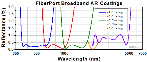
Figure 2.1 Each FiberPort lens is available with -A (350 - 700 nm or 400 - 700 nm), -B (600 - 1050 nm or 650 - 1050 nm), -C (1050 - 1620 nm or 1050 - 1700 nm), -D (1.8 - 2.4 µm), or -E (2.0 - 5.0 µm) coating. Please refer to the tables below for the specific wavelength range of each FiberPort lens.
Thermal Stability
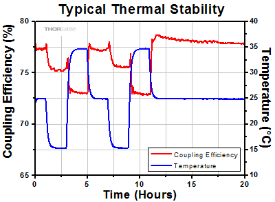
The thermal stability of the FiberPort was measured by changing the temperature of the environment by ±10 °C, and measuring the coupling efficiency as it varied with the temperature. These measurements were taken using a PAF2P-11A on an FB-38 FiberBench. A 635 nm source was used with single mode fiber. Please note that the thermal stability depends highly on the components and system setup.
Results:
The ~5% change in coupling efficiency is a result of the movement of all components in this FiberBench/FiberPort system. This change results in approximately 0.5 µm movement of the beam spot relative to the fiber core. After the temperature has changed, upon returning to the original temperature, the coupling efficiency returns to within 1% of the original value.
 Click to Enlarge
Figure 2.2 Thermal Stability Measurement of a PAF2P-11A FiberPort
Fine Axis Repeatability
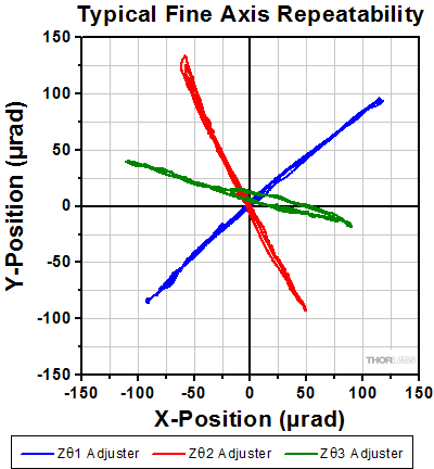
The repeatability of the Zθ adjustments was measured by translating the Zθ adjusters by 200-300 µrad and returning to the starting position at approximately (0,0). This was done three times. To measure this movement, a beam emitted from the FiberPort was transmitted to a CCD beam profiler. These measurements were done with the PAF2P-11A with an input wavelength of 635 nm.
Results:
As seen in Figure 2.3, these FiberPorts exhibit good repeatability and low hysteresis. These values are typical and will change based on the selected wavelength and focal length of the FiberPort.
Click to Enlarge
Figure 2.3 Repeatability Measurement of the Zθ Adjustments of a PAF2P-11A FiberPort
DESIGN FEATURES
External SM1 Threading
For integration into many of our optomechanical components, the FiberPort has an SM1 (1.035"-40)external threading.
Locking Collars
The locking collars on the Zθ adjusters fix the alignment position using the included spanner wrench. The collars can be locked without affecting even single mode alignments. They also prevent overtravel of the Zθ adjuster screws.Matched Material CTEs
The materials used have matched coefficients of thermal expansion (CTEs) to ensure optimal thermal performance. Additionally, the lens cell and tilt plate are made of hardened stainless steel for additional stability.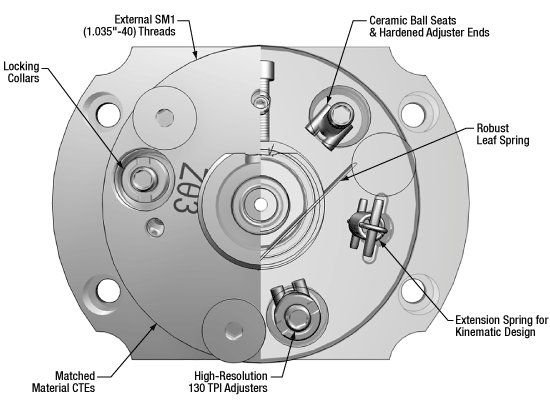
Figure 3.1 External (Left) and Internal (Right) FiberPort Features
Ceramic Ball Seats & Hardened Adjuster Ends
The long-wearing ceramic ball seats and the hardened adjuster ends ensure a secure fit and thermal stability.Robust Leaf Spring
The new leaf spring geometry reduces the risk of a bent leaf spring, ensuring repeatable and consistent travel in X and Y while minimizing hysteresis.Kinematic Design
The extension springs follow the dowel-and-spring design of our kinematic mounts, making the adjustments more repeatable and consistent.130 TPI Adjusters
The high-resolution adjusters allow for fine translation of the tilt plate.Additional Information
Click on the boxes below for more details.
These FiberPorts are especially designed to counteract common misalignment errors in an optical setup, namely temperature-induced hysteresis and crosstalk. Hours of extensive research, multiple design efforts using sophisticated design tools, and months of rigorous testing went into choosing the best components that allow the FiberPort to provide ultra-stable performance. Please see the Graphs tab for more information.
Because the temperature in most labs fluctuates, all mounts in an alignment-sensitive optical setup must intrinsically minimize any thermally induced misalignments. Stainless steel, with its low coefficient of thermal expansion, was chosen to compose the FiberPort to minimize these effects. Additionally, the lens cell and tilt plate are made of hardened stainless steel for additional durability.
In order to minimize positional drift and backlash, it is necessary to limit the amount of play in the adjusters, as well as the amount of lubricant used. When an adjustment is made to an actuator, the lubricant is displaced out of some places to build up in others. This non-equilibrium distribution of lubricant will slowly relax back into an equilibrium state. However, this process may cause the tilt plate to move. The FiberPort uses adjusters matched to the body that exceed all industry standards, so very little adjuster lubricant is needed. As a result, the FiberPort's alignment is extremely stable even after being adjusted. In addition, these adjusters have a smooth feel that allows the user to make small, repeatable adjustments.
These FiberPorts feature a longer leaf spring than the previous generation of FiberPorts, lowering the risk of a bent spring. This also provides a more consistent counterforce against the lens cell, making translation of the lens cell in the X and Y directions more predictable while allowing for full travel.
Adjustments in the Z or Zθ direction use high-resolution 130 TPI adjusters, allowing for fine movements. Additionally, there is an integrated travel limit for these adjusters, preventing overtravel that can force the lens cell off the X and Y adjusters.
Crosstalk is minimized by carefully controlling the dimensional tolerances, material properties, and finish of the components. Standard metal-to-metal actuator contact points will wear down over time; to prevent this, ceramic seats are used at all three contact points between the tilt plate and actuators. These ceramic seats, in conjunction with the hardened stainless steel actuator tips, maintain the integrity of the contact surfaces over time.
While not necessary for most applications in a lab setting, the position of the lens cell and the tilt plate can be locked. The lens cell can be locked by using the included locking screw. The tilt plate's position can be fixed by tightening the Zθ locking collars; this prevents the adjusters from being turned so the tilt plate cannot be translated. Single mode alignment is maintained when using these collars.
Our standard kinematic mounts utilize a dowel-and-spring and ball bearing design for adjustments. This allows for consistent and repeatable movement. The FiberPorts are similarly constructed; they have extension springs to actuate the tilt plate, as well as robust ball seats and adjuster ball ends.
The outer diameter of the FiberPort has SM1 (1.035"-40) threading that is compatible with many of our optomechanical components, including SM1 lens tubes and a variety of fixed mounts. If desired, the FiberPort can be secured into one of these components by the use of SM1 threaded retaining rings.
ALIGNMENT PROCEDURE
Alignment Procedures
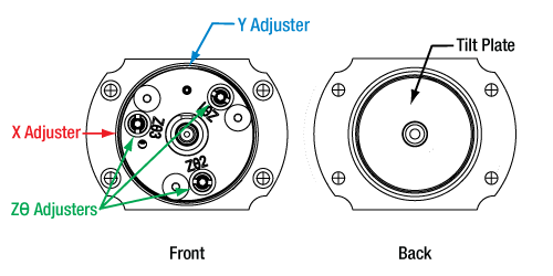
All FiberPorts contain a lens cell magnetically attached to a tilt plate that can be adjusted directly in the X and Y directions. Tip/Tilt adjustments along the optical axis are made by incremental adjustments of the Zθ adjusters, marked Zθ1, Zθ2, and Zθ3. These adjusters actuate the tilt plate. Translation in the Z-axis is made by uniformly turning the Zθ adjusters. We recommend using a low-power, visible alignment laser in all of the following adjustments.
These sections provide recommendations on how to use your FiberPort based on your application. Regardless of application, the Pre-alignment section should be read first. Please note that your FiberPort comes collimated for a specific wavelength as provided in their mechanical drawings, which can be found by clicking on the red document icon:![]() . After pre-aligning your FiberPort, the Collimating with a FiberPort section provides instructions on how to use your FiberPort as a collimator, while the Coupling into Fiber via FiberPort section provides instructions on how to couple single mode or multimode fiber using your FiberPort.
. After pre-aligning your FiberPort, the Collimating with a FiberPort section provides instructions on how to use your FiberPort as a collimator, while the Coupling into Fiber via FiberPort section provides instructions on how to couple single mode or multimode fiber using your FiberPort.
Pre-alignment
Click to Enlarge
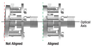
Figure 4.3 The tilt plate must be orthogonal to the beam axis for optimal alignment.
Before attempting to collimate or couple fiber with your FiberPort, it is crucial to ensure that the FiberPort is properly aligned in such a way that the tilt plate is orthogonal to the beam axis. If alignment is not done, coupling efficiencies will be lower than optimal, regardless of care taken later in the alignment process. If your FiberPort has been adjusted since purchase or requires collimation at a different wavelength, please follow the steps below to provide the best performance.
Aligning the Tilt Plate
With the laser off, center the lens by eye in the tilt plate aperture by turning the X and Y adjustment screws. The tilt plate must be flat against the FiberPort body and orthogonal to the beam axis. This must be done fairly precisely, and can be achieved one of the following ways:
Click to Enlarge
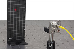
Figure 4.4 Aligning the Tilt Plate on a FiberPort using a TPSM1 Magnetic Alignment Grid
Using Input Laser (Recommended)
- Securely mount the FiberPort so it does not move during alignment.
- Turn the Zθ adjusters counter-clockwise until it is clear that they are no longer translating the tilt plate1.
- Insert a visible fiber laser2.
- Aim the beam at an alignment screen3.
- Turn each Zθ adjuster clockwise until the beam position is affected. Once each adjuster has just begun to affect position, the adjusters are in contact with the tilt plate. If done carefully, the tilt plate is still flush against the body of the FiberPort and is orthogonal to the optical axis.4
With No Input Laser
- If you are familiar with FiberPorts or if you are using a FiberPort with a 2.0 - 5.0 µm coating2, it is possible to align the tilt plate by feel alone.
- Turn the Zθ adjusters counter-clockwise until it is clear that they are no longer translating the tilt plate1.
- Carefully turn the Zθ adjusters clockwise until the resistance on the turn increases5.
- The adjusters are contacting the tilt plate when resistance is first met. If done carefully, the tilt plate is still flush against the body of the FiberPort and orthogonal to the optical axis4.
Common Issues
- I am unsure how far to unscrew the Zθ adjusters: Do not completely unscrew the Zθ adjusters.They should not be removed from the FiberPort.
- I cannot see the beam exiting the FiberPort: FiberPorts with a 2.0 - 5.0 µm coating will not transmit visible light. Aligning these FiberPorts With No Input Laser is recommended.
- I am unsure how to tell if the adjustments are affecting the beam diameter: It is easiest to see the beam diameter change when using an alignment screen with sufficiently small gradations.
- I do not know what the beam should look like: Since the Zθ adjusters are nearly completely unscrewed, the beam coming out of the FiberPort will be diverging. As a result, the farther downstream the screen is from the source, the easier the change will be to see. Additionally, ensure that the alignment screen that is being used has sufficiently fine gradations for your beam size.
- I do not know if I have made the correct adjustments: It may take several attempts to get the exact location. Do not actuate past when first resistance is felt.
Common Alignment Setups
There are multiple ways to configure an alignment setup. A common method of alignment is to use two mirrors and two irises, as seen in Figure 4.5 and 4.6. Alternatively, a FiberBench, seen in Figure 4.7, can provide a quick and compact way to utilize two FiberPorts in your system.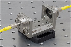
Click to Enlarge
Figure 4.7 A FiberBench provides a stable and quick way to integrate multiple FiberPorts into your system. A single-axis FB-51W FiberBench shown here.
 Click for Details
 Click for Details
- Ensure that the center of your mirrors, irises, and FiberPort are centered on the same optical axis. Our cage system and FiberBench systems can simplify this step.
- If using an FC/PC or FC/APC connector, make sure that the key on your fiber connector is aligned with your FiberPort. If using polarization-maintaining fiber, the bulkhead of the FiberPort can be rotated to match the fiber's polarization. This should be done as early as possible in the alignment process. Please see the Operation tab for more information.
- Align the mirror closest to the beam source with the iris it is closest to by placing a laser viewing card or aligment target directly after that iris. Partially close the iris until the beam spot begins to disappear. If one side of the beam is clipped first, adjust the mirror so that the beam is more centered with the iris. Align the other mirror and iris with each other in the same way.
- Repeat steps 2 and 3 until both mirrors and irises are aligned.
Collimating with a FiberPort
Step 1
Start with a pre-aligned FiberPort, as discussed in the Pre-alignment section above.Step 2
Check for collimation by measuring the beam diameter close to and downstream from your source1.
Step 3
Uniformly turn the Zθ adjusters clockwise by aligning your ball driver with the adjusters so that the number of rotations can be counted. Each adjuster must receive the same number of rotations to ensure the lens remains orthogonal to the beam axis and beam quality is preserved2.
Step 4
After each set of adjustments, measure the beam diameter from the same locations in step 2. If the beam is converging, the lens is too far away from the fiber. If the beam is diverging, the lens is too close to the fiber. Adjust the Zθ adjusters according to Figure 4.8. Once the downstream beam diameter is approximately equal to the beam's diameter near the source, your beam is collimated.
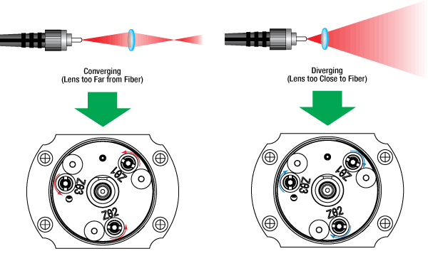
Figure 4.8 After adjusting the Zθ adjusters of a FiberPort to collimate a beam, check whether the beam is collimated. If the beam is converging, the lens is too far away from the fiber and the adjusters should be turned counterclockwise. If the beam is diverging, the lens is too close to the fiber and the adjusters should be turned clockwise.
Common Issues
- I cannot tell if my beam is collimated: The further from the source you measure, the easier it is to view the difference in beam diameter.
- Even though my X and Y position look correct, there is still an offset in the beam: Please ensure that care has been taken in pre-alignment. See the Pre-alignment section for more information.
Coupling into Fiber via FiberPort
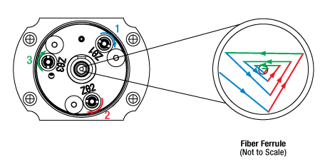 Figure 4.9 When turning each adjuster by equal increments, the beam traces a triangular pattern of changing width. The maximum power is seen not at either end of each turn's travel range, but in the middle when the beam is closest to the fiber's core. The beam's path is shown with point of view of the fiber that is being coupled into.
 Principle
While translation in the X- and Y- directions can be directly made by using their respective adjusters, translation in the Z-direction must be made by incremental tip/tilt adjustments using the three Zθ adjusters. As a result, the beam's path as the adjusters are turned may not be intuitive. Equal rotations to each of the Zθ adjusters result in the beam spot tracing a triangle around the core of the fiber, as illustrated in Figure 4.9. Once some measureable output exists, a typical alignment strategy would consist of turning each screw to maximize the output, and then continuing to turn slightly beyond maximum (about 95% of your local max). This must be done for each adjuster, and in the same order for each trio of adjustments1. This method prevents the power from being stuck at a local maximum. The maximum seen in each passing will continue to increase until the lens-to-fiber spacing is optimized (spot size is minimized), and a global maximum is reached. This strategy has the effect of translating the beam in a triangle of decreasing width with each set of adjustments.
Note that the typical maximum coupling efficiency is highly dependent on the system configuration and setup. Most configurations will achieve efficiencies between 60% and 80%. This efficiency can be improved upon by ensuring precise alignment with all system components, and verifying the compatibility of all components. Efficiencies below 50% may indicate significant component mismatch or alignment error.
Step 3
Choose an sequence to make your adjustments, and keep to that sequence1 . Turn each Zθ adjuster clockwise to maximize the output, then continue to turn slightly beyond local maxima (to ~95% of your local maximum). If turning an adjuster clockwise decreases output, skip that adjuster for that round of adjustments and repeat. Once the local maxima values begin to decrease, reverse the direction, and turn each adjuster to maximize the output, and not beyond.
Step 2
Insert a multimode (MM) fiber that is compatible with your system2 into the FiberPort and a power meter. Maximize the X and Y alignment by observing where the intensity peaks for each position. Once a maximum is reach, these adjusters should not be changed unless SM fiber is later used.
Step 1
Start with a pre-aligned FiberPort, as discussed in the Pre-alignment section above.
Step 6 (Optional)
If desired, the adjusters can be locked via the locking collars by the use of the included SPW403 spanner wrench. Additionally, the lens cell can be locked in place by installing the included 0-80 screw located in the 4 o'clock position of the front face of the FiberPort.
Single Mode Fiber Only
Step 5
Repeat Step 3. The adjustments will need to be smaller, as the system will be more sensitive. If adjustment of all screws in either direction lowers the output, the beam spot may be centered on the fiber core, but be improperly focused. Turn each adjuster a small amount (1/16th turn) in the same direction, then maximize each Zθ adjuster. If the new maximum is lower than the previous, turn each Zθ adjuster a small amount in the other direction and maximize. Repeat until absolute maximum is found.
Step 4
If coupling into a SM fiber, exchange the MM fiber with a SM fiber. The intensity measured by the power meter will likely drop significantly.
Common Issues
- I do not know what order to turn the adjusters: For instance, if you chose to adjust Zθ3, then Zθ1, then Zθ2, ensure you continue in this order for each set of adjustments.
- I do not know what fiber is most compatible with my system: Please see the Selection Guide tab for more information
OPERATION

Click to Enlarge
Figure 5.1 Internal Mechanism of the FiberPort With and Without the Outer Body Removed
X-Y Adjustment

Click to Enlarge
Figure 5.5 SHCS in the Side of the FiberPort for X-Y MLC Translation
| Table 5.4 Specifications | |
|---|---|
| Screw Size | 0-80 |
| Hex Size | 0.05" (1.3 mm) |
| Adjustment per Revolution | 317 µm |
| Translation Range | ±0.7 mm |
The magnetic lens cell (MLC) can be translated in X-Y, independently from the tilt plate, using the socket head cap screws (SHCS) in the side of the FiberPort body, highlighted in red and blue in Figure 5.5. Each adjuster is labeled as X and Y for easy and quick identification. The travel range of the lens in the X and Y directions is ±0.7 mm. See Table 5.4 for additional specifications for our X-Y adjuster screws. Note that when a FiberPort is used in a standard collimation or coupling application, only a small portion of this translation range is needed.
X-Y translation is performed independently from angular and Z-axis adjustments. The lens cell, which is magnetically attached to the tilt plate, rests on a leaf spring that provides a counterforce. The resistance of the adjustments made with these screws can be changed using the X-Y tension adjusters discussed below; each adjuster has been highlighted with the same color as its tension adjuster here. The X-Y motion can be locked in place using the locking screw discussed below.
Zθ Adjustment

Click to Enlarge
Figure 5.3 Zθ Adjusters on the FiberPort for Tilt Plate Actuation
| Table 5.2 Specifications | |
|---|---|
| Screw Size | M2 x 0.2 |
| Hex Size | 0.05" (1.3 mm) |
| Adjustment per Revolution |
200 µm |
| Translation Range | ±1.0 mm |
Each FiberPort consists of a lens cell that is magnetically adhered to a tilt plate. This tilt plate is actuated using three Zθ adjusters, highlighted in green in Figure 5.3. Each adjuster is labeled with Zθ1, Zθ2, or Zθ3 so it is easy to tell which adjuster has been or will be adjusted. Turning each adjuster in equal increments enables Z-translation along the optical axis of the FiberPort. The Z-axis translation range is ±1.0 mm. See Table 5.2 for additional specifications for our Zθ adjuster screws.
Once final adjustments are made, the position of the tilt plate can be locked via the included locking collars and SPW403 spanner wrench. These adjusters are lockable while maintaining single mode alignment.
The mechanics behind translation of the tilt plate is very similar to the dowel-and-spring construction of our kinematic mounts. Each adjuster has a hardened steel ball-end that rides in a ceramic ball seat. Both the ball-end and ceramic seat are attached using a high temperature, low outgassing epoxy to provide a stable, long wearing kinematic system. The extension springs provide counterforce against the fine adjust screws.
X-Y Lock
Click to Enlarge
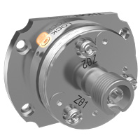
Figure 5.9 Setscrew on the Bottom of the FiberPort to Lock X and Y Adjustment Screw Positions
| Table 5.8 Specifications | |
|---|---|
| Screw Size | 0-80 |
| Hex Size | 0.05" (1.3 mm) |
A setscrew on the bottom of the Fiberport can be used to retain the position of the X and Y adjustment screws, highlighted in orange in Figure 5.9. Most applications do not require locking the FiberPort. For example, if the FiberPort is in a low-vibration environment than the locking screw does not need to be engaged.
However, for situations where the FiberPort might undergo large vibrations or shock, such as shipping, the setscrew should be engaged. Using the locking screw can affect coupling; follow all applicable directions in the FiberPort manual when using the locking feature. Note that this locking screw is included but not installed when the FiberPort is shipped. See Table 5.8 for additional specifications for our setscrew.
X-Y Tension

Click to Enlarge
Figure 5.7 Tension Screws on the FiberPort for Adjusting X-Y Adjuster Tension
| Table 5.6 Specifications | |
|---|---|
| Screw Size | 0-80 |
| Hex Size | 0.028" (0.7 mm) |
Each X-Y adjuster can have its tension adjusted using the corresponding tension screws on the face of the FiberPort, highlighted in red and blue in Figure 5.7. By tightening the tension of an adjuster, it is easier to make small adjustments to the MLC without overshooting the desired position. Conversely, loosening the tensions makes it easier to make large adjustments without applying excessive force. See Table 5.6 for additional specifications for our tension screws.
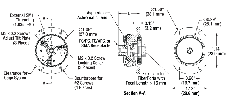
Figure 5.10 The L in the above mechanical drawing calls out the overall length from the front of the FiberPort, minus the connector bulkhead, to the front face of the mounting flange. This value depends on the focal length and the connector bulkhead. See the tables below for the exact length of each FiberPort.
SELECTION GUIDE
Introduction
Before selecting a FiberPort, it is crucial to consider:
- The wavelength of your source,
- The fiber type (single mode, multimode, or polarization maintaining),
- The fiber connector (FC/PC, FC/APC, or SMA), and
- The desired lens type (achromatic or aspheric).
With this information, it is possible to find what FiberPort is most compatible with your configuration. The method below illustrates the best way to find a FiberPort to use for coupling. This example considers a single mode fiber as the fiber that is being coupled. The calculations needed to determine whether a FiberPort is compatible with a single mode fiber are more complex than with a multimode fiber, which primarily considers the NA of the fiber and the lens.
Click on the FiberPort Selection Tool button to download a macro-enabled Excel file that can assist in finding the best FiberPort for your coupling application. For additional questions, please contact Tech Support.
Calculating the Effective Focal Length
Example:
- Wavelength: 633 nm
- Fiber: P1-630A-FC-2
- Collimated Beam Diameter Prior to Lens: Ø3 mm
The specifications for the P1-630A-FC-2, 633 nm, FC/PC single mode patch cable indicate that the 1/e2 mode field diameter (MFD) is 4.3 μm at 633 nm. The MFD should equal the diffraction-limited spot size Øspot, which is given by the following equation:

Here, f is the focal length of the lens, λ is the wavelength of the input light, and D is the 1/e2 diameter of collimated beam incident on the lens. Solving for the desired focal length of the collimating lens yields:

Thorlabs offers a large selection of FiberPorts. You'll note that the FiberPort with a focal length closest to 16 mm has a focal length of 15.3 mm (Item # PAF2P-15A), while also meeting the requirements for fiber connector type and antireflection coating range. This FiberPort also has a clear aperture that is larger than the collimated beam diameter. Therefore, this is the best option given the initial parameters (i.e., a P1-630A-FC-2 single mode fiber and a collimated beam diameter of 3 mm).
For optimum coupling, the spot size of the focused beam must be less than the MFD of the single mode fiber. As a result, if a FiberPort is not available that provides an exact match, then choose the FiberPort with a focal length that is shorter than the calculation above yields. Alternatively, if the clear aperture of the lens is large enough, the beam can be expanded before the lens, which has the result of reducing the spot size of the focused beam.
Please note that the NA values in the specification tables below are the numerical apertures of the lenses, not the required numerical aperture of the fiber you are using. As long as the lens NA is smaller than the NA of your fiber, you should be able to couple light. Please note that if your collimated beam diameter is smaller than the clear aperture of the lens you will need to recalculate the NA using the beam diameter. For best results, Thorlabs recommends using the equations above when choosing a FiberPort, or to use the selection tool linked above.
Selecting a Lens
When selecting a FiberPort, it is essential to ensure that the lens included in the FiberPort is compatible with your setup. In particular, the wavelength of the laser source must fall within the AR coating range of the lens, and the spot radius and focal shift should perform in such a way that is beneficial to your system.

Click to Enlarge
Figure 6.1 Each FiberPort lens is available with -A (350 - 700 nm or 400 - 700 nm), -B (600 - 1050 nm or 650 - 1050 nm), -C (1050 - 1620 nm or 1050 - 1700 nm), -D (1.8 - 2.4 µm), or -E (2.0 - 5.0 µm) coating. Please refer to the tables below for the specific wavelength range of each FiberPort lens.
AR Coatings
The lenses in Thorlabs’ FiberPorts use our -A (350 - 700 nm or 400 - 700 nm), -B (600 - 1050 nm or 650 - 1050 nm), -C (1050 - 1620 nm or 1050 - 1700 nm), -D (1800 - 2400 nm), or -E (2000 - 5000 nm) AR coatings. Figure 6.1 shows the typical per-surface reflectance of each AR coating. Each AR-coated lens is housed in a FiberPort package designed to be compatible with FC/PC-, FC/APC-, or SMA-terminated fibers. Care should be taken in selecting a FiberPort to make sure the correct fiber/connector/FiberPort combination is selected. AR-coating information and connector compatibility for each FiberPort are outlined in the tables below. Contact Tech Support for assistance.
Note: The C coating wavelength range specification was recently updated from 1050 - 1620 nm to 1050 - 1700 nm. All optics in stock currently have a C coating with a wavelength range of 1050 - 1700 nm. However, we are in the process of updating our documentation, and so some individual optics may still be presented with the old wavelength range on our website.
Aspheric vs. Achromatic FiberPort Performance
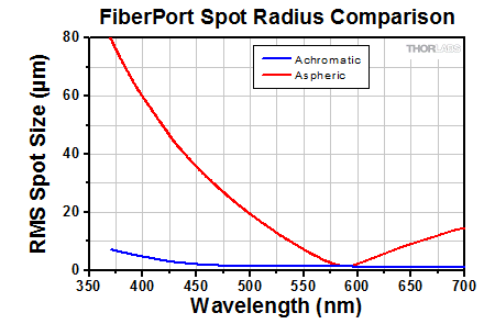
Thorlabs' achromatic FiberPorts utilize cemented doublets designed to minimize chromatic aberrations, making them ideal for collimating broadband light sources or sources with multiple discrete wavelengths. The small focal length shifts experienced by an achromatic doublet allow the FiberPort to be used over a broad wavelength range without the need for realignment (see the Graphs tab for more details).
Click to Enlarge
Figure 6.2 The performance of the achromatic doublet used in an achromatic FiberPort is compared to the aspheric lens used in a FiberPort with the same effective focal length, for a collimated beam focused onto a fiber. The lens is aligned to focus the light onto the fiber at 580 nm. Over a given wavelength range, the achromatic doublet produces a focused spot on the fiber, while the aspheric lens produces a series of wavelength dependent foci along its optical axis due to chromatic focal shift. Since the fiber's position was fixed at the focus of the aspheric lens, the spot size changed drastically with wavelength. However, appropriate adjustment of the fiber’s position as the wavelength is changed can minimize
this effect.

Click to Enlarge
Figure 6.3 This graph represents the focal length shift for the same setup described in the plot to the left. Both lenses have a similar focal length (f) at ~580 nm. Overall, the focal shift experienced by the aspheric lens in the range 475 nm - 655 nm (except ~580 nm) is approximately an order of magnitude larger than that of the achromatic doublet. For wavelengths less than 580 nm, the beam comes to a focus at a distance <f and longer wavelengths are focused at a distance >f.
CALCULATIONS
The calculations below can be used to theoretically approximate the divergence angle, maximum waist distance, and output diameter of a beam through a fiber collimator. For a macro-enabled Excel file with these and other useful calculations when working with fiber collimators, please click on the Fiber Collimator Calculator button. It is recommended to download and open the file in the Excel desktop application, as some features are not supported in the web version of Excel. The file includes calculations for the following parameters:
- Full Divergence Angle
- Maximum Waist Distance
- Output Beam Diameter
- Beam Diameter at a Certain Distance Away
- Fiber Coupling Efficiency
Please note that macros must be enabled to use the Excel file. To enable macros, click the "Enable Content" button in the yellow message bar upon opening the file.
Theoretical Approximation of the Divergence Angle
The full-angle beam divergence listed in the specifications tables is the theoretically-calculated value associated with the fiber collimator. This divergence angle is easy to approximate theoretically using the formula below as long as the light emerging from the fiber has a Gaussian intensity profile. Consequently, the formula works well for single mode fibers, but it will underestimate the divergence angle for multimode (MM) fibers since the light emerging from an MM fiber has a non-Gaussian intensity profile.
The full divergence angle (in degrees) is given by

where MFD is the mode field diameter and f is the focal length of the collimator. (Note: MFD and f must have the same units in this equation).
Example:
When the PAF2-A4A collimator is used with a single mode fiber such as the 460HP such that MFD = 3.5 µm and f = 4.0 mm, the divergence angle is
θ ≈ (0.0035 mm / 4.0 mm) * (180 / 3.1416) ≈ 0.050° or 0.875 mrad.
Theoretical Approximation of the Maximum Waist Distance
The maximum waist distance, which is the furthest distance from the lens the waist can be located in order to maintain collimation, may be approximated by

where f is the focal length of the collimator, λ is the wavelength of light used, and MFD is the mode field diameter. (Note: λ, MFD, and f must have the same units in this equation).
Example:
When the PAF2-A4A collimator is used with a single mode fiber such as the 460HP such that MFD = 3.5 µm, f = 4.0 mm, and λ = 450 nm, then the maximum waist distance is
zmax = 4.0 mm + [(2 * (4.0 mm)2 * 0.00045 mm) / (3.1416 * (0.0035 mm)2)] = 378 mm.
Theoretical Approximation of the Output Beam Diameter
The output beam diameter can be approximated from

where λ is the wavelength of light being used, MFD is the mode field diameter, and f is the focal length of the collimator. (Note: MFD and f must have the same units in this equation).
Example:
When the PAF2-A4A collimator (f = 4.0 mm) is used with the 460HP fiber (MFD = 3.5 µm) and 450 nm light, the output beam diameter is
d ≈ (4 * 0.00045 mm) * [4.0 mm / (3.1416 * 0.0035 mm)] = 0.65 mm.
FIBERPORT MOUNTS
| FiberPort Cage Mount | FiberPort Post Mount | ||
|---|---|---|---|
 Click to Enlarge Click to Enlarge |
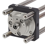
The CP08FP FiberPort Cage Mount is designed to center a FiberPort inside a 30 mm cage system. The CP08FP secures to the four ER rods of a 30 mm cage assembly. Four included 2-56 stainless steel socket head screws secure a FiberPort to the adapter. The CP08FP has internal SM1 (1.035"-40) threading, enabling it to be used with our extensive line of Ø1" lens tubes, and also 8-32 or M4 taps for post mounting. | 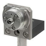 Click to Enlarge |
The HCP Post Mounting Bracket has four 2-56 threaded holes for securing a FiberPort to the front plate. The bottom of the L-bracket can be easily attached to an optical table, breadboard, or post, since it has 8-32- and M4-threaded holes, as well as a 1/4" (M6) counterbored hole. |
| FiberPort Standard HeNe Adapter | FiberPort 5/8"-32 Threaded HeNe Adapter | ||
 Click to Enlarge |
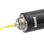
The HCL HeNe to FiberPort Adapter attaches a FiberPort directly to the front of a HeNe laser with an industry-standard four-bolt pattern. For additional mounting options, the HCL features internal C-Mount (1.000"-32) threading, which is utilized on some lasers. All mounting screws are included. See Section 6.3 of the FiberPort manual (available as a PDF here) for details. | 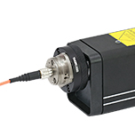 Click to Enlarge |
The HCL2 Self-Contained HeNe to FiberPort Adapter, which features external 5/8"-32 threading, allows a FiberPort coupler to be attached directly to the threaded aperture of our self-contained HeNe lasers or any other 5/8"-32 tapped hole. A slip-plate design allows the position of the FiberPort to be shifted and locked to maximize coupling efficiency. FiberPort mounting screws are included. See Section 6.3 of the FiberPort manual (available as a PDF here) for details. |
| FiberPort and FiberBench | |||
 Click to Enlarge |
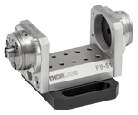
Thorlabs' fiber-to-fiber U-Benches consist of a FiberBench base combined with two FiberPorts. The U-Benches allow for easy access to the optical beam and are ideal for fiber-to-fiber applications that incorporate multiple components and require the utmost in stability. Thorlabs offers a complete line of optical subassemblies that can be placed into the beam path. We also offer our FiberBenches bundled with two compatible FiberPorts. | ||
INSIGHTS
Insights into Optical Fiber
Scroll down to read about:
- When does NA provide a good estimate of the fiber's acceptance angle?
- Why is MFD an important coupling parameter for single mode fibers?
- Does NA provide a good estimate of beam divergence from a single mode fiber?
Click here for more insights into lab practices and equipment.
When does NA provide a good estimate of the fiber's acceptance angle?
Click to Enlarge
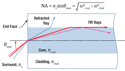
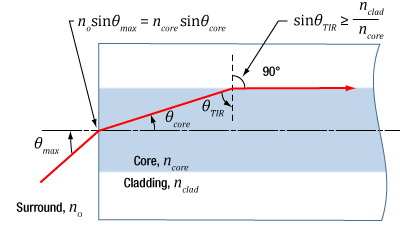
Figure 192A Rays incident at angles ≤θmax will be captured by the cores of multimode fiber, since these rays experience total internal reflection at the interface between core and cladding.
Click to Enlarge
Figure 192B The behavior of the ray at the boundary between the core and cladding, which depends on their refractive indices, determines whether the ray incident on the end face is coupled into the core. The equation for NA can be found using geometry and the two equations noted at the top of this figure.
Numerical aperture (NA) provides a good estimate of the maximum acceptance angle for most multimode fibers, as shown in Figure 192A. This relationship should not be used for single mode fibers.
NA and Acceptance Angle
Incident light is modeled as rays to obtain the relationship between NA and the maximum acceptance angle (θmax ), which describes the fiber's ability to gather light from off-axis sources. The equation at the top of Figure 192A can be used to determine whether rays traced from different light sources will be coupled into the fiber's core.
Rays with an angle of incidence ≤θmax are totally internally reflected (TIR) at the boundary between the fiber's core and cladding. As these rays propagate down the fiber, they remain trapped in the core.
Rays with angles of incidence larger than θmax refract at the interface between core and cladding, and this light is eventually lost from the fiber.
Geometry Defines the Relationship
The relationship among NA, θmax , and the refractive indices of the core and cladding, ncore and nclad , respectively, can be found using the geometry diagrammed in Figure 192B. This geometry illustrates the most extreme conditions under which TIR will occur at the boundary between the core and cladding.
The equations at the top of Figure 192B are expressions of Snell's law and describe the rays' behavior at both interfaces. Note that the simplification sin(90°) = 1 has been used. Only the indices of the core and cladding limit the value of θmax .
Angles of Incidence and Fiber Modes
When the angle of incidence is ≤θmax , the incident light ray is coupled into one of the multimode fiber's guided modes. Generally speaking, the lower the angle of incidence, the lower the order of the excited fiber mode. Lower-order modes concentrate most of their intensity near the center of the core. The lowest order mode is excited by rays incident normally on the end face.
Single Mode Fibers are Different
In the case of single mode fibers, the ray model in Figure 192B is not useful, and the calculated NA (acceptance angle) does not equal the maximum angle of incidence or describe the fiber's light gathering ability.
Single mode fibers have only one guided mode, the lowest order mode, which is excited by rays with 0° angles of incidence. However, calculating the NA results in a nonzero value. The ray model also does not accurately predict the divergence angles of the light beams successfully coupled into and emitted from single mode fibers. The beam divergence occurs due to diffraction effects, which are not taken into account by the ray model but can be described using the wave optics model. The Gaussian beam propagation model can be used to calculate beam divergence with high accuracy.
Date of Last Edit: Jan. 20, 2020
Why is MFD an important coupling parameter for single mode fibers?
Click to Enlarge
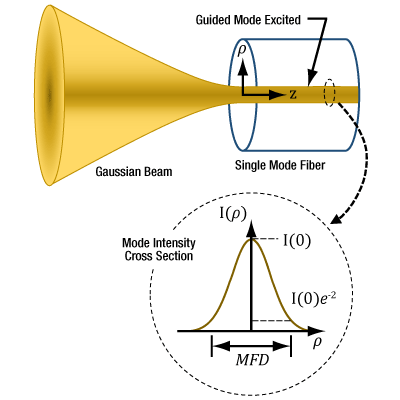
Figure 192C For maximum coupling efficiency into single mode fibers, the light should be an on-axis Gaussian beam with its waist located at the fiber's end face, and the waist diameter should equal the MFD. The beam output by the fiber also resembles a Gaussian with these characteristics. In the case of single mode fibers, the ray optics model and NA are inadequate for determining coupling conditions. The mode intensity (I ) profile across the radius ( ρ ) is illustrated.
As light propagates down a single mode fiber, the beam maintains a cross sectional profile that is nearly Gaussian in shape. The mode field diameter (MFD) describes the width of this intensity profile. The better an incident beam matches this intensity profile, the larger the fraction of light coupled into the fiber. An incident Gaussian beam with a beam waist equal to the MFD can achieve particularly high coupling efficiency.
Using the MFD as the beam waist in the Gaussian beam propagation model can provide highly accurate incident beam parameters, as well as the output beam's divergence.
Determining Coupling Requirements
A benefit of optical fibers is that light carried by the fibers' guided mode(s) does not spread out radially and is minimally attenuated as it propagates. Coupling light into one of a fiber's guided modes requires matching the characteristics of the incident light to those of the mode. Light that is not coupled into a guided mode radiates out of the fiber and is lost. This light is said to leak out of the fiber.
Single mode fibers have one guided mode, and wave optics analysis reveals the mode to be described by a Bessel function. The amplitude profiles of Gaussian and Bessel functions closely resemble one another, which is convenient since using a Gaussian function as a substitute simplifies the modeling the fiber's mode while providing accurate results (Kowalevicz).
Figure 192C illustrates the single mode fiber's mode intensity cross section, which the incident light must match in order to couple into the guided mode. The intensity (I ) profile is a near-Gaussian function of radial distance ( ρ ). The MFD, which is constant along the fiber's length, is the width measured at an intensity equal to the product of e-2 and the peak intensity. The MFD encloses ~86% of the beam's power.
Since lasers emitting only the lowest-order transverse mode provide Gaussian beams, this laser light can be efficiently coupled into single mode fibers.
Coupling Light into the Single Mode Fiber
To efficiently couple light into the core of a single-mode fiber, the waist of the incident Gaussian beam should be located at the fiber's end face. The intensity profile of the beam's waist should overlap and match the characteristics of the mode intensity cross section. The required incident beam parameters can be calculated using the fiber's MFD with the Gaussian beam propagation model.
The coupling efficiency will be reduced if the beam waist is a different diameter than the MFD, the cross-sectional profile of the beam is distorted or shifted with respect to the modal spot at the end face, and / or if the light is not directed along the fiber's axis.
References
Kowalevicz A and Bucholtz F, "Beam Divergence from an SMF-28 Optical Fiber (NRL/MR/5650--06-8996)." Naval Research Laboratory, 2006.
Date of Last Edit: Feb. 28, 2020
Why is MFD an important coupling parameter for single mode fibers?
Significant error can result when the numerical aperture (NA) is used to estimate the cone of light emitted from, or that can be coupled into, a single mode fiber. A better estimate is obtained using the Gaussian beam propagation model to calculate the divergence angle. This model allows the divergence angle to be calculated for whatever beam spot size best suits the application.
Since the mode field diameter (MFD) specified for single mode optical fibers encloses ~86% of the beam power, this definition of spot size is often appropriate when collimating light from and focusing light into a single mode fiber. In this case, to a first approximation and when measured in the far field,
 , , |
is the divergence or acceptance angle (θSM ), in radians. This is half the full angular extent of the beam, it is wavelength  )
)
| Rayleigh Range: | ||
 |
||
| Beam Radius at Distance z: | ||
 |
||
|
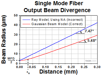
Figure 194D These curves illustrate the consequence of using NA to calculate the divergence (θSM ) of light output from a single mode fiber. Significant error in beam spot diameter can be avoided by using the Gaussian beam propagation model. This plot models a beam from SM980-5.8-125. The values used for NA and MFD were 0.13 and 6.4 µm, respectively. The operating wavelength was 980 nm, and the Rayleigh range was 32.8 µm. |
||
Gaussian Beam Approach
Although a diverging cone of light is emitted from the end face of a single mode optical fiber, this light does not behave as multiple rays travelling at different angles to the fiber's axis.
Instead, this light resembles and can be modeled as a single Gaussian beam. The emitted light propagates similarly to a Gaussian beam since the guided fiber mode that carried the light has near-Gaussian characteristics.
The divergence angle of a Gaussian beam can differ substantially from the angle calculated by assuming the light behaves as rays. Using the ray model, the divergence angle would equal sin-1(NA). However, the relationship between NA and divergence angle is only valid for highly multimode fibers.
Figure 194D illustrates that using the NA to estimate the divergence angle can result in significant error. In this case, the divergence angle was needed for a point on the circle enclosing 86% of the beam's optical power. The intensity of a point on this circle is a factor of 1/e2 lower than the peak intensity.
Equations (2) and (3) were used to accurately model the divergence of the beam emitted from the single mode fiber's end face. The values used to complete the calculations, including the fiber's MFD, NA, and operating wavelength are given in Figure 194D's caption. This rate of beam divergence assumes a beam size defined by the 1/e2 radius, is nonlinear for distances z < zR, and is approximately linear in the far field (z >> zR).
The angles noted on the plot were calculated from each curve's respective slope. When the far field approximation given by Equation (1) is used, the calculated divergence angle is 0.098 radians (5.61°).
References
Kowalevicz A and Bucholtz F, "Beam Divergence from an SMF-28 Optical Fiber (NRL/MR/5650--06-8996)." Naval Research Laboratory, 2006.
Date of Last Edit: Feb. 28, 2020
Content improved by our readers!
COLLIMATOR GUIDE
Fiber Collimator Selection Guide
Click on the collimator type or photo to view more information about each type of collimator.
| Type | Description | |
|---|---|---|
| Fixed FC, APC, or SMA Fiber Collimators |  |
These fiber collimation packages are pre-aligned to collimate light from an FC/PC-, FC/APC-, or SMA-terminated fiber. Each collimation package is factory aligned to provide diffraction-limited performance for wavelengths ranging from 405 nm to 4.55 µm. Although it is possible to use the collimator at detuned wavelengths, they will only perform optimally at the design wavelength due to chromatic aberration, which causes the effective focal length of the aspheric lens to have a wavelength dependence. |
| Air-Spaced Doublet, Large Beam Collimators |  |
For large beam diameters (Ø5.3 - Ø8.5 mm), Thorlabs offers FC/APC, FC/PC, and SMA air-spaced doublet collimators. These collimation packages are pre-aligned at the factory to collimate a laser beam propagating from the tip of an FC or SMA-terminated fiber and provide diffraction-limited performance at the design wavelength. |
| Triplet Collimators | 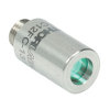 |
Thorlabs' High Quality Triplet Fiber Collimation packages use air-spaced triplet lenses that offer superior beam quality performance when compared to aspheric lens collimators. The benefits of the low-aberration triplet design include an M2 term closer to 1 (Gaussian), less divergence, and less wavefront error. |
| Achromatic Collimators for Multimode Fiber | 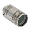 |
Thorlabs' High-NA Achromatic Collimators pair a meniscus lens with an achromatic doublet for high performance across the visible to near-infrared spectrum with low spherical aberration. Designed for use with high-NA multimode fiber, these collimators are ideal for Optogenetics and Fiber Photometry applications. |
| Reflective Collimators | 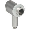 |
Thorlabs' metallic-coated Reflective Collimators are based on a 90° off-axis parabolic mirror. Mirrors, unlike lenses, have a focal length that remains constant over a broad wavelength range. Due to this intrinsic property, a parabolic mirror collimator does not need to be adjusted to accommodate various wavelengths of light, making them ideal for use with polychromatic light. Our fixed reflective collimators are recommended for collimating single and multimode fiber and coupling into multimode fiber. These collimators are available with UV-enhanced aluminum or protected silver reflective coatings and with FC/PC, FC/APC, or SMA connector compatibility. |
| Compact Reflective Collimators | 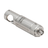 |
Thorlabs' Compact Reflective Collimators incorporate a 90° off-axis parabolic mirror with a protected silver coating. Because the focal length is independent of wavelength for an off-axis parabolic mirror, they are ideal for use with polychromatic light. Our fixed reflective collimators are recommended for collimating single and multimode fiber and coupling into multimode fiber. These collimators are directly compatible with our 16 mm cage system. They are available with FC/PC, FC/APC, or SMA connector inputs. |
| Adjustable Reflective Collimators |  |
Thorlabs' Adjustable Focus Reflective Collimators use a 90° off-axis parabolic (OAP) mirror with a protected silver coating to collimate light from a fiber or couple light into a fiber. The adjustable fiber-to-OAP distance, combined with the OAP having a constant focal length across wavelengths, makes these collimators ideal for optimizing collimation or coupling of polychromatic light with single mode or multimode fiber. These adjustable collimators have a 15.0 mm or 33.0 mm reflected focal length and are available with FC/PC, FC/APC, or SMA connectors. |
| Polaris Kinematic, Fixed Focus Collimators |  |
Polaris® Kinematic, Fixed Focus Collimators combine the high-quality beam output of our fixed focus collimation packages with the remarkable mechanical properties of our Polaris® mounts, making them the ultimate solution for fiber collimation applications requiring stringent long-term alignment stability. These fiber collimation packages are pre-aligned to collimate light from an FC/PC-terminated fiber with diffraction-limited performance at one of four alignment wavelengths between 532 nm and 850 nm. |
| FiberPorts |  |
These compact, ultra-stable FiberPort micropositioners provide an easy-to-use, stable platform for coupling light into and out of FC/PC, FC/APC, or SMA terminated optical fibers. It can be used with single mode, multimode, or PM fibers and can be mounted onto a post, stage, platform, or laser. The built-in aspheric or achromatic lens is available with five different AR coatings and has five degrees of alignment adjustment (3 translational and 2 pitch). The compact size and long-term alignment stability make the FiberPort an ideal solution for fiber coupling, collimation, or incorporation into OEM systems. |
| Adjustable Fiber Collimators |  |
These collimators are designed to connect onto the end of an FC/PC, FC/APC, or SMA connector and contain an AR-coated aspheric lens. The distance between the aspheric lens and the tip of the fiber can be adjusted to compensate for focal length changes or to recollimate the beam at the wavelength and distance of interest. |
| Achromatic Fiber Collimators with Adjustable Focus |  |
Thorlabs' Achromatic Fiber Collimators with Adjustable Focus are designed with an effective focal length (EFL) of 20 mm, 40 mm, or 80 mm, have optical elements broadband AR coated for one of three wavelength ranges, and are available with FC/PC, FC/APC, or SMA905 connectors. A four-element, air-spaced lens design produces superior beam quality (M2 close to 1) and less wavefront error when compared to aspheric lens collimators. These collimators can be used for free-space coupling into a fiber, collimation of output from a fiber, or in pairs for collimator-to-collimator coupling over long distances, which allows the beam to be manipulated prior to entering the second collimator. |
| Zoom Fiber Collimators |  |
These collimators provide a variable focal length between 6 and 18 mm, while maintaining the collimation of the beam. As a result, the size of the beam can be changed without altering the collimation. This universal device saves time previously spent searching for the best suited fixed fiber collimator and has a very broad range of applications. They are offered with FC/PC, FC/APC, or SMA905 connectors with three different antireflection wavelength ranges to choose from. |
| Single Mode Pigtailed Collimators | 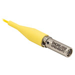 |
Our single mode pigtailed collimators come with one meter of fiber, consist of an AR-coated aspheric lens pre-aligned with respect to a fiber, and are collimated at one of eight wavelengths: 532 nm, 633 nm, 780 nm, 850 nm, 1030 nm, 1064 nm, 1310 nm, or 1550 nm. Although it is possible to use the collimator at any wavelength within the coating range, the coupling loss will increase as the wavelength is detuned from the design wavelength. |
| Polarization Maintaining Pigtailed Collimators | 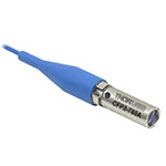 |
Our polarization maintaining pigtailed collimators come with one meter of fiber, consist of an AR-coated aspheric lens pre-aligned with respect to a fiber, and are collimated at one of five wavelengths: 633 nm, 780 nm, 980 nm, 1064 nm, or 1550 nm. Custom wavelengths and connectors are available as well. A line is engraved along the outside of the housing that is parallel to the fast axis. As such, it can be used as a reference when polarized light is launched accordingly. Although it is possible to use the collimator at any wavelength within the coating range, the coupling loss will increase as the wavelength is detuned from the design wavelength. |
| GRIN Fiber Collimators | 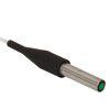 |
Thorlabs offers gradient index (GRIN) fiber collimators that are aligned at a variety of wavelengths from 630 to 1550 nm and have either FC terminated, APC terminated, or unterminated fibers. Our GRIN collimators feature a Ø1.8 mm clear aperture, are AR-coated to ensure low back reflection into the fiber, and are coupled to standard single mode or graded-index multimode fibers. |
| GRIN Lenses | 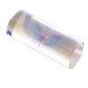 |
These graded-index (GRIN) lenses are AR coated for applications at 630, 830, 1060, 1300, or 1560 nm that require light to propagate through one fiber, then through a free-space optical system, and finally back into another fiber. They are also useful for coupling light from laser diodes into fibers, coupling the output of a fiber into a detector, or collimating laser light. Our GRIN lenses are designed to be used with our Pigtailed Glass Ferrules and GRIN/Ferrule sleeves. |
Achromatic FiberPorts for FC/PC and FC/APC Connectors (EFL 4.0 mm or 7.5 mm)
FiberPorts with an effective focal length of ≤7.5 mm can be used with both FC/PC and FC/APC connectors, as the 5-axis adjustment combined with the short focal length leads to negligible off-axis sensitivity.
| Item # | EFL | Input MFDa,b |
Output 1/e2 Waist Diametera |
Max Waist Distancea,c |
Divergencea | EFL Shiftd (Click for Plot) |
Lens Characteristics | Length Lg | |||
|---|---|---|---|---|---|---|---|---|---|---|---|
| CAe | NA | AR Rangef | Material (Click for Plot) |
||||||||
| PAF2-A4A | 4.0 mm | 3.5 µm | 0.65 mm | 378 mm | 0.875 mrad | 1.8 mm | 0.22 | 350 - 700 nm | N-SK16 / N-LASF9 | 0.70" (17.7 mm) | |
| PAF2-A4B | 4.0 mm | 5.0 µm | 0.87 mm | 350 mm | 1.250 mrad | 1.8 mm | 0.22 | 600 - 1050 nm | N-LAK22 / N-SF6HT | 0.70" (17.7 mm) | |
| PAF2-A4C | 4.0 mm | 10.4 µm | 0.76 mm | 150 mm | 2.600 mrad | 1.8 mm | 0.22 | 1050 - 1620 nm | S-PHM52/S-NPH2 | 0.70" (17.7 mm) | |
| PAF2-A7A | 7.5 mm | 3.5 µm | 1.23 mm | 1323 mm | 0.467 mrad | 4.5 mm | 0.30 | 400 - 700 nm | N-BAF10 / N-SF6HT | 0.70" (17.7 mm) | |
| PAF2-A7B | 7.5 mm | 5.0 µm | 1.62 mm | 1225 mm | 0.667 mrad | 4.5 mm | 0.30 | 650 - 1050 nm | N-BAF10 / N-SF6HT | 0.70" (17.7 mm) | |
| PAF2-A7C | 7.5 mm | 10.4 µm | 1.42 mm | 521 mm | 1.387 mrad | 4.5 mm | 0.30 | 1050 - 1700 nm | N-LAK22 / N-SF6 | 0.70" (17.7 mm) | |
Part Number | Description | Price | Availability |
|---|---|---|---|
PAF2-A4A | Achromatic FiberPort, FC/PC & FC/APC, f = 4.0 mm, 350 - 700 nm, Ø0.65 mm Waist | $749.42 | In Stock Overseas |
PAF2-A4B | Achromatic FiberPort, FC/PC & FC/APC, f = 4.0 mm, 600 - 1050 nm, Ø0.87 mm Waist | $749.42 | In Stock Overseas |
PAF2-A4C | Achromatic FiberPort, FC/PC & FC/APC, f = 4.0 mm, 1050 - 1620 nm, Ø0.76 mm Waist | $749.42 | Lead Time |
PAF2-A7A | Customer Inspired! Achromatic FiberPort, FC/PC & FC/APC, f = 7.5 mm, 400 - 700 nm, Ø1.23 mm Waist | $749.42 | Today |
PAF2-A7B | Customer Inspired! Achromatic FiberPort, FC/PC & FC/APC, f = 7.5 mm, 650 - 1050 nm, Ø1.62 mm Waist | $749.42 | Today |
PAF2-A7C | Customer Inspired! Achromatic FiberPort, FC/PC & FC/APC, f = 7.5 mm, 1050 - 1700 nm, Ø1.42 mm Waist | $749.42 | Today |
Achromatic FiberPorts for FC/PC Connectors (EFL 10 mm or 15 mm)
| Item # | EFL | Input MFDa,b |
Output 1/e2 Waist Diametera |
Max Waist Distancea,c | Divergencea | EFL Shiftd (Click for Plot) |
Lens Characteristics | Length Lg | |||
|---|---|---|---|---|---|---|---|---|---|---|---|
| CAe | NA | AR Rangef | Material (Click for Plot) |
||||||||
| PAF2P-A10A | 10.0 mm | 3.5 µm | 1.64 mm | 2349 mm | 0.350 mrad | >4.5 mm | 0.23 | 400 - 700 nm | N-BAK4/SF5 | 0.87" (22.2 mm) | |
| PAF2P-A10B | 10.0 mm | 5.0 µm | 2.16 mm | 2175 mm | 0.500 mrad | >4.5 mm | 0.23 | 650 - 1050 nm | N-LAK22/N-SF6HT | 0.87" (22.2 mm) | |
| PAF2P-A10C | 10.0 mm | 10.4 µm | 1.99 mm | 922 mm | 0.990 mrad | >4.5 mm | 0.23 | 1050 - 1700 nm | N-LAK22/N-SF6 | 0.87" (22.2 mm) | |
| PAF2P-A15A | 15.0 mm | 3.5 µm | 2.46 mm | 5277 mm | 0.233 mrad | >4.5 mm | 0.15 | 400 - 700 nm | N-BK7/SF2 | 0.87" (22.2 mm) | |
| PAF2P-A15B | 15.0 mm | 5.0 µm | 3.25 mm | 4885 mm | 0.333 mrad | >4.5 mm | 0.15 | 650 - 1050 nm | N-LAK22/N-SF6HT | 0.87" (22.2 mm) | |
| PAF2P-A15C | 15.0 mm | 10.4 µm | 2.85 mm | 2068 mm | 0.693 mrad | >4.5 mm | 0.15 | 1050 - 1700 nm | N-BAF10/N-SF6 | 0.87" (22.2 mm) | |
Part Number | Description | Price | Availability |
|---|---|---|---|
PAF2P-A10A | Customer Inspired! Achromatic FiberPort, FC/PC, f = 10.0 mm, 400 - 700 nm, Ø1.64 mm Waist | $735.45 | Today |
PAF2P-A10B | Customer Inspired! Achromatic FiberPort, FC/PC, f = 10.0 mm, 650 - 1050 nm, Ø2.16 mm Waist | $735.45 | Today |
PAF2P-A10C | Customer Inspired! Achromatic FiberPort, FC/PC, f = 10.0 mm, 1050 - 1700 nm, Ø1.99 mm Waist | $735.45 | Today |
PAF2P-A15A | Customer Inspired! Achromatic FiberPort, FC/PC, f = 15.0 mm, 400 - 700 nm, Ø2.46 mm Waist | $735.45 | Today |
PAF2P-A15B | Customer Inspired! Achromatic FiberPort, FC/PC, f = 15.0 mm, 650 - 1050 nm, Ø3.25 mm Waist | $735.45 | Today |
PAF2P-A15C | Customer Inspired! Achromatic FiberPort, FC/PC, f = 15.0 mm, 1050 - 1700 nm, Ø2.85 mm Waist | $735.45 | In Stock Overseas |
Achromatic FiberPorts for FC/APC Connectors (EFL 10 mm or 15 mm)
| Item # | EFL | Input MFDa,b |
Output 1/e2 Waist Diametera |
Max Waist Distancea,c | Divergencea | EFL Shiftd (Click for Plot) |
Lens Characteristics | Length Lg | |||
|---|---|---|---|---|---|---|---|---|---|---|---|
| CAe | NA | AR Rangef | Material (Click for Plot) |
||||||||
| PAF2A-A10A | 10.0 mm | 3.5 µm | 1.64 mm | 2349 mm | 0.350 mrad | >4.5 mm | 0.23 | 400 - 700 nm | N-BAK4/SF5 | 0.88" (22.4 mm) | |
| PAF2A-A10B | 10.0 mm | 5.0 µm | 2.16 mm | 2175 mm | 0.500 mrad | >4.5 mm | 0.23 | 650 - 1050 nm | N-LAK22/N-SF6HT | 0.88" (22.4 mm) | |
| PAF2A-A10C | 10.0 mm | 10.4 µm | 1.99 mm | 922 mm | 0.990 mrad | >4.5 mm | 0.23 | 1050 - 1700 nm | N-LAK22/N-SF6 | 0.88" (22.4 mm) | |
| PAF2A-A15A | 15.0 mm | 3.5 µm | 2.46 mm | 5277 mm | 0.233 mrad | >4.5 mm | 0.15 | 400 - 700 nm | N-BK7/SF2 | 0.88" (22.4 mm) | |
| PAF2A-A15B | 15.0 mm | 5.0 µm | 3.25 mm | 4885 mm | 0.333 mrad | >4.5 mm | 0.15 | 650 - 1050 nm | N-LAK22/N-SF6HT | 0.88" (22.4 mm) | |
| PAF2A-A15C | 15.0 mm | 10.4 µm | 2.85 mm | 2068 mm | 0.693 mrad | >4.5 mm | 0.15 | 1050 - 1700 nm | N-BAF10/N-SF6 | 0.88" (22.4 mm) | |
Part Number | Description | Price | Availability |
|---|---|---|---|
PAF2A-A10A | Customer Inspired! Achromatic FiberPort, FC/APC, f = 10.0 mm, 400 - 700 nm, Ø1.64 mm Waist | $735.45 | Today |
PAF2A-A10B | Customer Inspired! Achromatic FiberPort, FC/APC, f = 10.0 mm, 650 - 1050 nm, Ø2.16 mm Waist | $735.45 | Today |
PAF2A-A10C | Customer Inspired! Achromatic FiberPort, FC/APC, f = 10.0 mm, 1050 - 1700 nm, Ø1.99 mm Waist | $735.45 | Today |
PAF2A-A15A | Customer Inspired! Achromatic FiberPort, FC/APC, f = 15.0 mm, 400 - 700 nm, Ø2.46 mm Waist | $735.45 | Today |
PAF2A-A15B | Customer Inspired! Achromatic FiberPort, FC/APC, f = 15.0 mm, 650 - 1050 nm, Ø3.25 mm Waist | $735.45 | In Stock Overseas |
PAF2A-A15C | Customer Inspired! Achromatic FiberPort, FC/APC, f = 15.0 mm, 1050 - 1700 nm, Ø2.85 mm Waist | $735.45 | Today |
Achromatic FiberPorts for SMA Connectors (EFL 4.0 mm or 7.5 mm)
| Item # | EFL | Input MFDa,b |
Output 1/e2 Waist Diametera |
Max Waist Distancea,c |
Divergencea | EFL Shiftd (Click for Plot) |
Lens Characteristics | Length Lg | |||
|---|---|---|---|---|---|---|---|---|---|---|---|
| CAe | NA | AR Rangef | Material (Click for Plot) |
||||||||
| PAF2S-A4A | 4.0 mm | 3.5 µm | 0.65 mm | 378 mm | 0.875 mrad | 1.8 mm | 0.22 | 350 - 700 nm | N-SK16 / N-LASF9 | 0.87" (22.0 mm) | |
| PAF2S-A4B | 4.0 mm | 5.0 µm | 0.87 mm | 350 mm | 1.250 mrad | 1.8 mm | 0.22 | 600 - 1050 nm | N-LAK22 / N-SF6HT | 0.87" (22.0 mm) | |
| PAF2S-A4C | 4.0 mm | 10.4 µm | 0.76 mm | 150 mm | 2.600 mrad | 1.8 mm | 0.22 | 1050 - 1620 nm | S-PHM52/S-NPH2 | 0.87" (22.0 mm) | |
| PAF2S-A7A | 7.5 mm | 3.5 µm | 1.23 mm | 1323 mm | 0.467 mrad | 4.5 mm | 0.30 | 400 - 700 nm | N-BAF10 / N-SF6HT | 0.87" (22.0 mm) | |
| PAF2S-A7B | 7.5 mm | 5.0 µm | 1.62 mm | 1225 mm | 0.667 mrad | 4.5 mm | 0.30 | 650 - 1050 nm | N-BAF10 / N-SF6HT | 0.87" (22.0 mm) | |
| PAF2S-A7C | 7.5 mm | 10.4 µm | 1.42 mm | 521 mm | 1.387 mrad | 4.5 mm | 0.30 | 1050 - 1700 nm | N-LAK22 / N-SF6 | 0.87" (22.0 mm) | |
Part Number | Description | Price | Availability |
|---|---|---|---|
PAF2S-A4A | Customer Inspired! Achromatic FiberPort, SMA, f = 4.0 mm, 350 - 700 nm, Ø0.65 mm Waist | $735.45 | In Stock Overseas |
PAF2S-A4B | Customer Inspired! Achromatic FiberPort, SMA, f = 4.0 mm, 600 - 1050 nm, Ø0.87 mm Waist | $735.45 | Today |
PAF2S-A4C | Customer Inspired! Achromatic FiberPort, SMA, f = 4.0 mm, 1050 - 1620 nm, Ø0.76 mm Waist | $735.45 | Today |
PAF2S-A7A | Achromatic FiberPort, SMA, f = 7.5 mm, 400 - 700 nm, Ø1.23 mm Waist | $735.45 | Today |
PAF2S-A7B | Achromatic FiberPort, SMA, f = 7.5 mm, 650 - 1050 nm, Ø1.62 mm Waist | $735.45 | Today |
PAF2S-A7C | Achromatic FiberPort, SMA, f = 7.5 mm, 1050 - 1700 nm, Ø1.62 mm Waist | $735.45 | Today |
Aspheric FiberPorts for FC/PC and FC/APC Connectors (EFL 7.5 mm or Less)
FiberPorts with an effective focal length of ≤7.5 mm can be used with both FC/PC and FC/APC connectors, as the 5-axis adjustment combined with the short focal length leads to negligible off-axis sensitivity.
| Item # | EFL | Input MFDa,b | Output 1/e2 Waist Diametera |
Max Waist Distancea,c |
Divergencea | Lens Characteristics | Length Lf | |||
|---|---|---|---|---|---|---|---|---|---|---|
| CAd | NA | AR Rangee | Material | |||||||
| PAF2-2A | 2.0 mm | 3.5 µm | 0.33 mm | 96 mm | 1.750 mrad | 2.0 mm | 0.50 | 350 - 700 nm | D-ZLAF52LA | 0.70" (17.7 mm) |
| PAF2-2B | 2.0 mm | 5.0 µm | 0.43 mm | 89 mm | 2.500 mrad | 2.0 mm | 0.50 | 600 - 1050 nm | D-ZLAF52LA | 0.70" (17.7 mm) |
| PAF2-2C | 2.0 mm | 10.4 µm | 0.38 mm | 38 mm | 5.200 mrad | 2.0 mm | 0.50 | 1050 - 1620 nm | D-ZLAF52LA | 0.70" (17.7 mm) |
| PAF2-4E | 4.0 mm | 14.80 µm | 1.17 mm | 162 mm | 3.700 mrad | 5.0 mm | 0.56 | 2.0 - 5.0 µm | Black Diamond-2 | 0.70" (17.7 mm) |
| PAF2-5A | 4.6 mm | 3.5 µm | 0.75 mm | 499 mm | 0.761 mrad | 4.9 mm | 0.53 | 350 - 700 nm | H-LAK54 | 0.70" (17.7 mm) |
| PAF2-5B | 4.6 mm | 5.0 µm | 1.00 mm | 463 mm | 1.087 mrad | 4.9 mm | 0.53 | 600 - 1050 nm | H-LAK54 | 0.70" (17.7 mm) |
| PAF2-5C | 4.6 mm | 10.4 µm | 0.87 mm | 198 mm | 2.261 mrad | 4.9 mm | 0.53 | 1050 - 1620 nm | H-LAK54 | 0.70" (17.7 mm) |
| PAF2-5D | 4.6 mm | 13.0 µm | 0.90 mm | 164 mm | 2.826 mrad | 4.9 mm | 0.53 | 1.8 - 2.4 µm | H-LAK54 | 0.70" (17.7 mm) |
| PAF2-7A | 7.5 mm | 3.5 µm | 1.23 mm | 1323 mm | 0.467 mrad | 4.5 mm | 0.30 | 350 - 700 nm | H-LAK54 | 0.70" (17.7 mm) |
| PAF2-7B | 7.5 mm | 5.0 µm | 1.62 mm | 1225 mm | 0.667 mrad | 4.5 mm | 0.30 | 600 - 1050 nm | H-LAK54 | 0.70" (17.7 mm) |
| PAF2-7C | 7.5 mm | 10.4 µm | 1.42 mm | 521 mm | 1.387 mrad | 4.5 mm | 0.30 | 1050 - 1620 nm | H-LAK54 | 0.70" (17.7 mm) |
Part Number | Description | Price | Availability |
|---|---|---|---|
PAF2-2A | FiberPort, FC/PC & FC/APC, f=2.0 mm, 350 - 700 nm, Ø0.33 mm Waist | $716.90 | Today |
PAF2-2B | FiberPort, FC/PC & FC/APC, f=2.0 mm, 600 - 1050 nm, Ø0.43 mm Waist | $716.90 | In Stock Overseas |
PAF2-2C | FiberPort, FC/PC & FC/APC, f=2.0 mm, 1050 - 1620 nm, Ø0.38 mm Waist | $716.90 | Today |
PAF2-4E | FiberPort, FC/PC & FC/APC, f=4.0 mm, 2.0 - 5.0 µm, Ø1.17 mm Waist | $1,168.88 | In Stock Overseas |
PAF2-5A | FiberPort, FC/PC & FC/APC, f=4.6 mm, 350 - 700 nm, Ø0.75 mm Waist | $674.10 | In Stock Overseas |
PAF2-5B | FiberPort, FC/PC & FC/APC, f=4.6 mm, 600 - 1050 nm, Ø1.00 mm Waist | $674.10 | Today |
PAF2-5C | FiberPort, FC/PC & FC/APC, f=4.6 mm, 1050 - 1620 nm, Ø0.87 mm Waist | $674.10 | Today |
PAF2-5D | FiberPort, FC/PC & FC/APC, f=4.6 mm, 1.8 - 2.4 µm, Ø0.90 mm Waist | $674.10 | Today |
PAF2-7A | FiberPort, FC/PC & FC/APC, f=7.5 mm, 350 - 700 nm, Ø1.23 mm Waist | $674.10 | Today |
PAF2-7B | FiberPort, FC/PC & FC/APC, f=7.5 mm, 600 - 1050 nm, Ø1.62 mm Waist | $674.10 | Today |
PAF2-7C | FiberPort, FC/PC & FC/APC, f=7.5 mm, 1050 - 1620 nm, Ø1.42 mm Waist | $674.10 | Today |
Aspheric FiberPorts for FC/PC Connectors (EFL 11 mm or Greater)
| Item # | EFL | Input MFDa,b | Output 1/e2 Waist Diametera |
Max Waist Distancea,c |
Divergencea | Lens Characteristics | Length Lf | |||
|---|---|---|---|---|---|---|---|---|---|---|
| CAd | NA | AR Rangee | Material | |||||||
| PAF2P-11A | 11.0 mm | 3.5 µm | 1.80 mm | 2841 mm | 0.318 mrad | 4.4 mm | 0.20 | 350 - 700 nm | H-LAK54 | 0.87" (22.0 mm) |
| PAF2P-11B | 11.0 mm | 5.0 µm | 2.38 mm | 2630 mm | 0.455 mrad | 4.4 mm | 0.20 | 600 - 1050 nm | H-LAK54 | 0.87" (22.0 mm) |
| PAF2P-11C | 11.0 mm | 10.4 µm | 2.09 mm | 1115 mm | 0.945 mrad | 4.4 mm | 0.20 | 1050 - 1620 nm | H-LAK54 | 0.87" (22.0 mm) |
| PAF2P-11D | 11.0 mm | 13.0 µm | 2.15 mm | 921 mm | 1.182 mrad | 4.4 mm | 0.20 | 1.8 - 2.4 µm | H-LAK54 | 0.87" (22.0 mm) |
| PAF2P-11E | 11.0 mm | 14.80 µm | 3.21 mm | 1203 mm | 1.345 mrad | 4.0 mm | 0.18 | 2.0 - 5.0 µm | Black Diamond-2 | 0.87" (22.0 mm) |
| PAF2P-15A | 15.3 mm | 3.5 µm | 2.52 mm | 5490 mm | 0.227 mrad | 5.0 mm | 0.16 | 350 - 700 nm | D-ZK3 | 0.87" (22.0 mm) |
| PAF2P-15B | 15.3 mm | 5.0 µm | 3.33 mm | 5082 mm | 0.325 mrad | 5.0 mm | 0.16 | 600 - 1050 nm | D-ZK3 | 0.87" (22.0 mm) |
| PAF2P-15C | 15.3 mm | 10.4 µm | 2.92 mm | 2151 mm | 0.675 mrad | 5.0 mm | 0.16 | 1050 - 1620 nm | D-ZK3 | 0.87" (22.0 mm) |
| PAF2P-15D | 15.3 mm | 13.0 µm | 3.00 mm | 1775 mm | 0.850 mrad | 5.0 mm | 0.16 | 1.8 - 2.4 µm | D-ZK3 | 0.87" (22.0 mm) |
| PAF2P-18A | 18.4 mm | 3.5 µm | 3.01 mm | 7936 mm | 0.190 mrad | 5.5 mm | 0.15 | 350 - 700 nm | D-ZK3 | 0.87" (22.0 mm) |
| PAF2P-18B | 18.4 mm | 5.0 µm | 3.98 mm | 7347 mm | 0.272 mrad | 5.5 mm | 0.15 | 600 - 1050 nm | D-ZK3 | 0.87" (22.0 mm) |
| PAF2P-18C | 18.4 mm | 10.4 µm | 3.49 mm | 3107 mm | 0.565 mrad | 5.5 mm | 0.15 | 1050 - 1620 nm | D-ZK3 | 0.87" (22.0 mm) |
| PAF2P-18D | 18.4 mm | 13.0 µm | 3.60 mm | 2564 mm | 0.707 mrad | 5.5 mm | 0.15 | 1.8 - 2.4 µm | D-ZK3 | 0.87" (22.0 mm) |
Part Number | Description | Price | Availability |
|---|---|---|---|
PAF2P-11A | FiberPort, FC/PC, f=11.0 mm, 350 - 700 nm, Ø1.80 mm Waist | $689.30 | Today |
PAF2P-11B | FiberPort, FC/PC, f=11.0 mm, 600 - 1050 nm, Ø2.38 mm Waist | $689.30 | Today |
PAF2P-11C | FiberPort, FC/PC, f=11.0 mm, 1050 - 1620 nm, Ø2.09 mm Waist | $689.30 | Today |
PAF2P-11D | FiberPort, FC/PC, f=11.0 mm, 1.8 - 2.4 μm, Ø2.15 mm Waist | $689.30 | Today |
PAF2P-11E | FiberPort, FC/PC, f=11.0 mm, 2.0 - 5.0 µm, Ø3.21 mm Waist | $1,132.51 | Today |
PAF2P-15A | FiberPort, FC/PC, f=15.3 mm, 350 - 700 nm, Ø2.52 mm Waist | $735.45 | Today |
PAF2P-15B | FiberPort, FC/PC, f=15.3 mm, 600 - 1050 nm, Ø3.33 mm Waist | $735.45 | Today |
PAF2P-15C | FiberPort, FC/PC, f=15.3 mm, 1050 - 1620 nm, Ø2.92 mm Waist | $735.45 | Today |
PAF2P-15D | FiberPort, FC/PC, f=15.3 mm, 1.8 - 2.4 µm, Ø3.00 mm Waist | $735.45 | Today |
PAF2P-18A | FiberPort, FC/PC, f=18.4 mm, 350 - 700 nm, Ø3.01 mm Waist | $749.42 | Today |
PAF2P-18B | FiberPort, FC/PC, f=18.4 mm, 600 - 1050 nm, Ø3.98 mm Waist | $749.42 | Today |
PAF2P-18C | FiberPort, FC/PC, f=18.4 mm, 1050 - 1620 nm, Ø3.49 mm Waist | $749.42 | Today |
PAF2P-18D | FiberPort, FC/PC, f=18.4 mm, 1.8 - 2.4 µm, Ø3.60 mm Waist | $749.42 | Today |
Aspheric FiberPorts for FC/APC Connectors (EFL Between 2 mm and 18.4 mm)
| Item # | EFL | Input MFDa,b | Output 1/e2 Waist Diametera |
Max Waist Distancea,c |
Divergencea | Lens Characteristics | Length Lf | |||
|---|---|---|---|---|---|---|---|---|---|---|
| CAd | NA | AR Rangee | Material | |||||||
| PAF2A-2A | 2.0 mm | 3.5 µm | 0.33 mm | 96 mm | 1.750 mrad | 2.0 mm | 0.50 | 350 - 700 nm | D-ZLAF52LA | 0.70" (17.9 mm) |
| PAF2A-2B | 2.0 mm | 5.0 µm | 0.43 mm | 89 mm | 2.500 mrad | 2.0 mm | 0.50 | 600 - 1050 nm | D-ZLAF52LA | 0.70" (17.9 mm) |
| PAF2A-2C | 2.0 mm | 10.4 µm | 0.38 mm | 38 mm | 5.200 mrad | 2.0 mm | 0.50 | 1050 - 1620 nm | D-ZLAF52LA | 0.70" (17.9 mm) |
| PAF2A-5A | 4.6 mm | 3.5 µm | 0.75 mm | 499 mm | 0.761 mrad | 4.9 mm | 0.53 | 350 - 700 nm | H-LAK54 | 0.70" (17.9 mm) |
| PAF2A-5B | 4.6 mm | 5.0 µm | 1.00 mm | 463 mm | 1.087 mrad | 4.9 mm | 0.53 | 600 - 1050 nm | H-LAK54 | 0.70" (17.9 mm) |
| PAF2A-5C | 4.6 mm | 10.4 µm | 0.87 mm | 198 mm | 2.261 mrad | 4.9 mm | 0.53 | 1050 - 1620 nm | H-LAK54 | 0.70" (17.9 mm) |
| PAF2A-7A | 7.5 mm | 3.5 µm | 1.23 mm | 1323 mm | 0.467 mrad | 4.5 mm | 0.30 | 350 - 700 nm | H-LAK54 | 0.70" (17.9 mm) |
| PAF2A-7B | 7.5 mm | 5.0 µm | 1.62 mm | 1225 mm | 0.667 mrad | 4.5 mm | 0.30 | 600 - 1050 nm | H-LAK54 | 0.70" (17.9 mm) |
| PAF2A-7C | 7.5 mm | 10.4 µm | 1.42 mm | 521 mm | 1.387 mrad | 4.5 mm | 0.30 | 1050 - 1620 nm | H-LAK54 | 0.70" (17.9 mm) |
| PAF2A-11A | 11.0 mm | 3.5 µm | 1.80 mm | 2841 mm | 0.318 mrad | 4.4 mm | 0.20 | 350 - 700 nm | H-LAK54 | 0.88" (22.4 mm) |
| PAF2A-11B | 11.0 mm | 5.0 µm | 2.38 mm | 2630 mm | 0.455 mrad | 4.4 mm | 0.20 | 600 - 1050 nm | H-LAK54 | 0.88" (22.4 mm) |
| PAF2A-11C | 11.0 mm | 10.4 µm | 2.09 mm | 1115 mm | 0.945 mrad | 4.4 mm | 0.20 | 1050 - 1620 nm | H-LAK54 | 0.88" (22.4 mm) |
| PAF2A-11D | 11.0 mm | 13.0 µm | 2.15 mm | 921 mm | 1.182 mrad | 4.4 mm | 0.20 | 1.8 - 2.4 µm | H-LAK54 | 0.88" (22.4 mm) |
| PAF2A-11E | 11.0 mm | 14.80 µm | 3.21 mm | 1203 mm | 1.345 mrad | 4.0 mm | 0.18 | 2.0 - 5.0 µm | Black Diamond-2 | 0.88" (22.4 mm) |
| PAF2A-15A | 15.3 mm | 3.5 µm | 2.52 mm | 5490 mm | 0.227 mrad | 5.0 mm | 0.16 | 350 - 700 nm | D-ZK3 | 0.88" (22.4 mm) |
| PAF2A-15B | 15.3 mm | 5.0 µm | 3.33 mm | 5082 mm | 0.325 mrad | 5.0 mm | 0.16 | 600 - 1050 nm | D-ZK3 | 0.88" (22.4 mm) |
| PAF2A-15C | 15.3 mm | 10.4 µm | 2.92 mm | 2151 mm | 0.675 mrad | 5.0 mm | 0.16 | 1050 - 1620 nm | D-ZK3 | 0.88" (22.4 mm) |
| PAF2A-15D | 15.3 mm | 13.0 µm | 3.00 mm | 1775 mm | 0.850 mrad | 5.0 mm | 0.16 | 1.8 - 2.4 µm | D-ZK3 | 0.88" (22.4 mm) |
| PAF2A-18A | 18.4 mm | 3.5 µm | 3.01 mm | 7936 mm | 0.190 mrad | 5.5 mm | 0.15 | 350 - 700 nm | D-ZK3 | 0.88" (22.4 mm) |
| PAF2A-18B | 18.4 mm | 5.0 µm | 3.98 mm | 7347 mm | 0.272 mrad | 5.5 mm | 0.15 | 600 - 1050 nm | D-ZK3 | 0.88" (22.4 mm) |
| PAF2A-18C | 18.4 mm | 10.4 µm | 3.49 mm | 3107 mm | 0.565 mrad | 5.5 mm | 0.15 | 1050 - 1620 nm | D-ZK3 | 0.88" (22.4 mm) |
| PAF2A-18D | 18.4 mm | 13.0 µm | 3.60 mm | 2564 mm | 0.707 mrad | 5.5 mm | 0.15 | 1.8 - 2.4 µm | D-ZK3 | 0.88" (22.4 mm) |
Part Number | Description | Price | Availability |
|---|---|---|---|
PAF2A-2A | FiberPort, FC/APC, f=2.0 mm, 350 - 700 nm, Ø0.33 mm Waist | $716.90 | Today |
PAF2A-2B | FiberPort, FC/APC, f=2.0 mm, 600 - 1050 nm, Ø0.43 mm Waist | $716.90 | Today |
PAF2A-2C | FiberPort, FC/APC, f=2.0 mm, 1050 - 1620 nm, Ø0.38 mm Waist | $716.90 | Lead Time |
PAF2A-5A | FiberPort, FC/APC, f=4.6 mm, 350 - 700 nm, Ø0.75 mm Waist | $674.10 | In Stock Overseas |
PAF2A-5B | FiberPort, FC/APC, f=4.6 mm, 600 - 1050 nm, Ø1.00 mm Waist | $674.10 | Today |
PAF2A-5C | FiberPort, FC/APC, f=4.6 mm, 1050 - 1620 nm, Ø0.87 mm Waist | $674.10 | Today |
PAF2A-7A | FiberPort, FC/APC, f=7.5 mm, 350 - 700 nm, Ø1.23 mm Waist | $674.10 | In Stock Overseas |
PAF2A-7B | FiberPort, FC/APC, f=7.5 mm, 600 - 1050 nm, Ø1.62 mm Waist | $674.10 | Today |
PAF2A-7C | FiberPort, FC/APC, f=7.5 mm, 1050 - 1620 nm, Ø1.42 mm Waist | $674.10 | Today |
PAF2A-11A | FiberPort, FC/APC, f=11.0 mm, 350 - 700 nm, Ø1.80 mm Waist | $689.30 | In Stock Overseas |
PAF2A-11B | FiberPort, FC/APC, f=11.0 mm, 600 - 1050 nm, Ø2.38 mm Waist | $689.30 | Today |
PAF2A-11C | FiberPort, FC/APC, f=11.0 mm, 1050 - 1620 nm, Ø2.09 mm Waist | $689.30 | Today |
PAF2A-11D | FiberPort, FC/APC, f=11.0 mm, 1.8 - 2.4 µm, Ø2.15 mm Waist | $689.30 | Today |
PAF2A-11E | Customer Inspired! FiberPort, FC/APC, f=11.0 mm, 2.0 - 5.0 µm, Ø3.21 mm Waist | $1,132.51 | Today |
PAF2A-15A | FiberPort, FC/APC, f=15.3 mm, 350 - 700 nm, Ø2.52 mm Waist | $735.45 | Today |
PAF2A-15B | FiberPort, FC/APC, f=15.3 mm, 600 - 1050 nm, Ø3.33 mm Waist | $735.45 | Today |
PAF2A-15C | FiberPort, FC/APC, f=15.3 mm, 1050 - 1620 nm, Ø2.92 mm Waist | $735.45 | Today |
PAF2A-15D | FiberPort, FC/APC, f=15.3 mm, 1.8 - 2.4 µm, Ø3.00 mm Waist | $735.45 | Today |
PAF2A-18A | FiberPort, FC/APC, f=18.4 mm, 350 - 700 nm, Ø3.01 mm Waist | $749.42 | Today |
PAF2A-18B | FiberPort, FC/APC, f=18.4 mm, 600 - 1050 nm, Ø3.98 mm Waist | $749.42 | Today |
PAF2A-18C | FiberPort, FC/APC, f=18.4 mm, 1050 - 1620 nm, Ø3.49 mm Waist | $749.42 | Today |
PAF2A-18D | FiberPort, FC/APC, f=18.4 mm, 1.8 - 2.4 µm, Ø3.60 mm Waist | $749.42 | Today |
Aspheric FiberPorts for SMA Connectors (EFL Between 2 mm and 18.4 mm)
| Item # | EFL | Input MFDa,b | Output 1/e2 Waist Diametera |
Max Waist Distancea,c |
Divergencea | Lens Characteristics | Length Lf | |||
|---|---|---|---|---|---|---|---|---|---|---|
| CAd | NA | AR Rangee | Material | |||||||
| PAF2S-2A | 2.0 mm | 3.5 µm | 0.33 mm | 96 mm | 1.750 mrad | 2.0 mm | 0.50 | 350 - 700 nm | D-ZLAF52LA | 0.87" (22.0 mm) |
| PAF2S-2B | 2.0 mm | 5.0 µm | 0.43 mm | 89 mm | 2.500 mrad | 2.0 mm | 0.50 | 600 - 1050 nm | D-ZLAF52LA | 0.87" (22.0 mm) |
| PAF2S-2C | 2.0 mm | 10.4 µm | 0.38 mm | 38 mm | 5.200 mrad | 2.0 mm | 0.50 | 1050 - 1620 nm | D-ZLAF52LA | 0.87" (22.0 mm) |
| PAF2S-4E | 4.0 mm | 14.80 µm | 1.17 mm | 162 mm | 3.700 mrad | 5.0 mm | 0.56 | 2.0 - 5.0 µm | Black Diamond-2 | 0.87" (22.0 mm) |
| PAF2S-5A | 4.6 mm | 3.5 µm | 0.75 mm | 499 mm | 0.761 mrad | 4.9 mm | 0.53 | 350 - 700 nm | H-LAK54 | 0.87" (22.0 mm) |
| PAF2S-5B | 4.6 mm | 5.0 µm | 1.00 mm | 463 mm | 1.087 mrad | 4.9 mm | 0.53 | 600 - 1050 nm | H-LAK54 | 0.87" (22.0 mm) |
| PAF2S-5C | 4.6 mm | 10.4 µm | 0.87 mm | 198 mm | 2.261 mrad | 4.9 mm | 0.53 | 1050 - 1620 nm | H-LAK54 | 0.87" (22.0 mm) |
| PAF2S-5D | 4.6 mm | 13.0 µm | 0.90 mm | 164 mm | 2.826 mrad | 4.9 mm | 0.53 | 1.8 - 2.4 µm | H-LAK54 | 0.87" (22.0 mm) |
| PAF2S-7A | 7.5 mm | 3.5 µm | 1.23 mm | 1323 mm | 0.467 mrad | 4.5 mm | 0.30 | 350 - 700 nm | H-LAK54 | 0.87" (22.0 mm) |
| PAF2S-7B | 7.5 mm | 5.0 µm | 1.62 mm | 1225 mm | 0.667 mrad | 4.5 mm | 0.30 | 600 - 1050 nm | H-LAK54 | 0.87" (22.0 mm) |
| PAF2S-7C | 7.5 mm | 10.4 µm | 1.42 mm | 521 mm | 1.387 mrad | 4.5 mm | 0.30 | 1050 - 1620 nm | H-LAK54 | 0.87" (22.0 mm) |
| PAF2S-11A | 11.0 mm | 3.5 µm | 1.80 mm | 2841 mm | 0.318 mrad | 4.4 mm | 0.20 | 350 - 700 nm | H-LAK54 | 1.04" (26.5 mm) |
| PAF2S-11B | 11.0 mm | 5.0 µm | 2.38 mm | 2630 mm | 0.455 mrad | 4.4 mm | 0.20 | 600 - 1050 nm | H-LAK54 | 1.04" (26.5 mm) |
| PAF2S-11C | 11.0 mm | 10.4 µm | 2.09 mm | 1115 mm | 0.945 mrad | 4.4 mm | 0.20 | 1050 - 1620 nm | H-LAK54 | 1.04" (26.5 mm) |
| PAF2S-11D | 11.0 mm | 13.0 µm | 2.15 mm | 921 mm | 1.182 mrad | 4.4 mm | 0.20 | 1.8 - 2.4 µm | H-LAK54 | 1.04" (26.5 mm) |
| PAF2S-11E | 11.0 mm | 14.80 µm | 3.21 mm | 1203 mm | 1.345 mrad | 4.0 mm | 0.18 | 2.0 - 5.0 µm | Black Diamond-2 | 1.04" (26.5 mm) |
| PAF2S-15A | 15.3 mm | 3.5 µm | 2.52 mm | 5490 mm | 0.227 mrad | 5.0 mm | 0.16 | 350 - 700 nm | D-ZK3 | 1.04" (26.5 mm) |
| PAF2S-15B | 15.3 mm | 5.0 µm | 3.33 mm | 5082 mm | 0.325 mrad | 5.0 mm | 0.16 | 600 - 1050 nm | D-ZK3 | 1.04" (26.5 mm) |
| PAF2S-15C | 15.3 mm | 10.4 µm | 2.92 mm | 2151 mm | 0.675 mrad | 5.0 mm | 0.16 | 1050 - 1620 nm | D-ZK3 | 1.04" (26.5 mm) |
| PAF2S-15D | 15.3 mm | 13.0 µm | 3.00 mm | 1775 mm | 0.850 mrad | 5.0 mm | 0.16 | 1.8 - 2.4 µm | D-ZK3 | 1.04" (26.5 mm) |
| PAF2S-18A | 18.4 mm | 3.5 µm | 3.01 mm | 7936 mm | 0.190 mrad | 5.5 mm | 0.15 | 350 - 700 nm | D-ZK3 | 1.04" (26.5 mm) |
| PAF2S-18B | 18.4 mm | 5.0 µm | 3.98 mm | 7347 mm | 0.272 mrad | 5.5 mm | 0.15 | 600 - 1050 nm | D-ZK3 | 1.04" (26.5 mm) |
| PAF2S-18C | 18.4 mm | 10.4 µm | 3.49 mm | 3107 mm | 0.565 mrad | 5.5 mm | 0.15 | 1050 - 1620 nm | D-ZK3 | 1.04" (26.5 mm) |
| PAF2S-18D | 18.4 mm | 13.0 µm | 3.60 mm | 2564 mm | 0.707 mrad | 5.5 mm | 0.15 | 1.8 - 2.4 µm | D-ZK3 | 1.04" (26.5 mm) |
Part Number | Description | Price | Availability |
|---|---|---|---|
PAF2S-2A | FiberPort, SMA, f=2.0 mm, 350 - 700 nm, Ø0.33 mm Waist | $689.30 | Today |
PAF2S-2B | FiberPort, SMA, f=2.0 mm, 600 - 1050 nm, Ø0.43 mm Waist | $689.30 | Today |
PAF2S-2C | FiberPort, SMA, f=2.0 mm, 1050 - 1620 nm, Ø0.38 mm Waist | $689.30 | Today |
PAF2S-4E | FiberPort, SMA, f=4.0 mm, 2.0 - 5.0 µm, Ø1.17 mm Waist | $1,064.02 | Today |
PAF2S-5A | FiberPort, SMA, f=4.6 mm, 350 - 700 nm, Ø0.75 mm Waist | $588.50 | Today |
PAF2S-5B | FiberPort, SMA, f=4.6 mm, 600 - 1050 nm, Ø1.00 mm Waist | $588.50 | Today |
PAF2S-5C | FiberPort, SMA, f=4.6 mm, 1050 - 1620 nm, Ø0.87 mm Waist | $588.50 | Today |
PAF2S-5D | FiberPort, SMA, f=4.6 mm, 1.8 - 2.4 µm, Ø0.90 mm Waist | $588.50 | Today |
PAF2S-7A | FiberPort, SMA, f=7.5 mm, 350 - 700 nm, Ø1.23 mm Waist | $588.50 | Today |
PAF2S-7B | FiberPort, SMA, f=7.5 mm, 600 - 1050 nm, Ø1.62 mm Waist | $588.50 | Today |
PAF2S-7C | FiberPort, SMA, f=7.5 mm, 1050 - 1620 nm, Ø1.42 mm Waist | $588.50 | Today |
PAF2S-11A | FiberPort, SMA, f=11.0 mm, 350 - 700 nm, Ø1.80 mm Waist | $588.50 | In Stock Overseas |
PAF2S-11B | FiberPort, SMA, f=11.0 mm, 600 - 1050 nm, Ø2.38 mm Waist | $588.50 | Today |
PAF2S-11C | FiberPort, SMA, f=11.0 mm, 1050 - 1620 nm, Ø2.09 mm Waist | $588.50 | Today |
PAF2S-11D | FiberPort, SMA, f=11.0 mm, 1.8 - 2.4 µm, Ø2.15 mm Waist | $588.50 | Today |
PAF2S-11E | FiberPort, SMA, f=11.0 mm, 2.0 - 5.0 µm, Ø3.21 mm Waist | $1,057.03 | Today |
PAF2S-15A | FiberPort, SMA, f=15.3 mm, 350 - 700 nm, Ø2.52 mm Waist | $689.30 | Today |
PAF2S-15B | FiberPort, SMA, f=15.3 mm, 600 - 1050 nm, Ø3.33 mm Waist | $689.30 | Today |
PAF2S-15C | FiberPort, SMA, f=15.3 mm, 1050 - 1620 nm, Ø2.92 mm Waist | $689.30 | Today |
PAF2S-15D | FiberPort, SMA, f=15.3 mm, 1.8 - 2.4 µm, Ø3.00 mm Waist | $689.30 | Today |
PAF2S-18A | FiberPort, SMA, f=18.4 mm, 350 - 700 nm, Ø3.01 mm Waist | $749.42 | Today |
PAF2S-18B | FiberPort, SMA, f=18.4 mm, 600 - 1050 nm, Ø3.98 mm Waist | $749.42 | Today |
PAF2S-18C | FiberPort, SMA, f=18.4 mm, 1050 - 1620 nm, Ø3.49 mm Waist | $749.42 | Today |
PAF2S-18D | FiberPort, SMA, f=18.4 mm, 1.8 - 2.4 µm, Ø3.60 mm Waist | $749.42 | Today |


