
 Laser Sources page for pricing and availability information" title="Visit the K-Cube®
K-Cube® Laser Sources
- Two Wavelengths Available: 635 nm and 1550 nm
- Single Mode Interface with FC/PC Output Connector
- Operates Using Top Panel Controls or Remote PC via USB
KLS1550
K-Cube® 1550 nm Laser Source
Shown with Included Mounting Plate
(Power Supply Sold Separately)
Kinesis Software Included
OVERVIEW
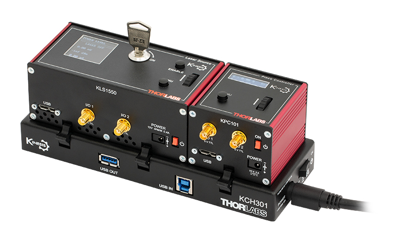
Click to Enlarge
Figure 1.2 A KCH301 USB Controller Hub with Installed KLS1550 and KPC101 K-Cube Modules
| Compact Light Source & Driver Modules |
|---|
| K-Cube Modulesa |
| Laser Diode Driver |
| Laser Sources |
| T-Cube Modulesa |
| High Power LED Driver |

Click to Enlarge
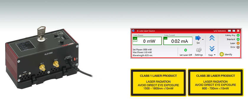
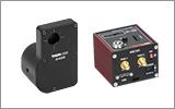
Figure 1.1 Top and Back Views of KLS635 Laser Source
(See the Pin Diagrams Tab for More Information)
Features
- Compact Footprint: 121.0 mm x 60.0 mm x 47.0 mm
- 635 nm or 1550 nm Wavelengths Available
- Single Mode Fiber Interface with FC/PC Bulkhead
- LCD Display Screen and Controls for Standalone Operation
- USB Connection for Remote PC-Controlled Operation
- SMA Input for Laser Intensity Control from External Source
- Two Bidirectional I/O Triggers (5 V TTL Signal)
- Safety Enable Key Switch and Laser Safety Interlock Jack
- Includes the Kinesis® Software Control Suite
- Software Compatible with Other Kinesis Controllers for Integrated Systems Development
- Single-Channel PSU Options Available Separately
- USB Controller Hubs for Operating Multiple K-Cubes® or T-Cubes™ (Sold Separately)
- Magnetic, Clip-On Optical Table Mounting Adapter Included
Thorlabs' K-Cube Laser Sources are fully functional, highly compact, fiber-coupled laser sources with a center wavelength of either 635 nm or 1550 nm. Each unit incorporates driver electronics and an FC/PC (2.1 mm wide key) fiber interface. The internally pigtailed Fabry-Perot laser diode is connected to the rear panel FC/PC output via a single mode fiber. With this fiber-to-fiber connection at the output, these devices deliver optical power more efficiently than air-to-fiber systems that use a receptacle with embedded optics. The laser can be operated independently via the top panel controls and display screen or remotely by PC via a USB connection. The output power is monitored continuously and a feedback circuit adjusts the laser power to achieve a constant output power.
The unit has a highly compact 121.0 mm x 60.0 mm x 47.0 mm footprint, allowing it to be positioned close to the rest of the system for added convenience when manually adjusting the laser output using the top panel controls. Tabletop operation also allows minimal cable lengths for easier cable management. A power switch on the front of the unit turns the K-Cube on and off. The top panel display screen enables operation as soon as the unit is turned on, without the need for connection to a PC. When the switch is turned off, the K-Cube saves all user-adjustable settings for the next session. Please note that the power switch should always be in the "off" position when plugging in or unplugging the unit. The laser must be turned off when connecting or disconnecting a fiber from the input. Please ensure the fiber tip and connector bulkhead are clean prior to use; the FBC250 Bulkhead and Connector Cleaner can be used to clean the bulkhead and connecting fiber.
USB connectivity provides easy 'Plug-and-Play' PC-controlled operation, and a suitable cable is included with each K-Cube laser source (USB 3.0 type A to USB 2.0 type Micro B). The Kinesis software package features .NET controls that can be used by third-party developers working in compatible languages such as C, C# and LabVIEW™ to create custom applications. For more details, please see the Kinesis Software and Kinesis Tutorials tabs.
Optical Table Mounting Plate
Each unit comes with a mounting plate that clips onto the base of the module. The plate contains two magnets for temporary placement on an optical table and two counterbored slots for 1/4"-20 (M6) cap screws for a more permanent placement on the tabletop.
Power Supply Options
The preferred power supply (single channel, multi-channel, or hub-based) depends on the end user's application and whether you already own compatible power supplies. To that end and in keeping with Thorlabs' green initiative, we do not ship these units bundled with a power supply.
Multiple units can be connected to a single PC by using the KCH301 or KCH601 USB Controller Hubs, available below, for applications involving multiple K-Cubes and/or T-Cubes. Please see the Mounting Options tab for more details. The KCH301 features three controller mounting bays while the KCH601 features six controller mounting bays. Note that these K-Cube laser sources occupy two mounting bays on the USB controller hubs.
All power supply options compatible with the K-Cube laser sources can be found below.
SPECS
| Item # | KLS635 | KLS1550 |
|---|---|---|
| Wavelength | 635 nm | 1550 nm |
| Maximum Output Power | 8.0 mW | 7.0 mW |
| Output Fiber Connector | FC/PC (Wide 2.1 mm Key Compatible) | |
| Stability | ±0.1 dB | |
| Display Accuracy | ±10% | |
| Set Point Resolution | 0.01 mW | |
| Modulation Input | 0 to 10 V = 0 to Full Power | |
| Modulation Bandwidth | Sine Wave: 600 Hz at 3 dB 1 kHz at 6 dB |
|
| EXT IN Input Impedancea | 16 kΩ | |
| Input Voltage | 15 V | |
| Operating Temperature | 15 to 35 °C | |
| Storage Temperature | 0 to 50 °C | |
| USB Connector Type | USB 3.0 | |
| USB Connection Speed | USB 1.1 Full Speed (12 Mbps) | |
| Housing Dimensions (W x D x H) | 121.0 mm x 60.0 mm x 47.0 mm (4.76" x 2.36" x 1.85") | |
| Weight | 350 g | 300 g |
PIN DIAGRAMS
Computer Connection
The USB 3.0 port is compatible with a USB 2.0 Micro B connector if the Micro B connector is plugged into the shaded region in the photo above. A USB 3.0 type A to type Micro B cable is included with the
I/O 1 & 2
SMA Female
These connectors provide a 5 V logic level input and output that can be configured to support triggering into and out of external devices. Each port can be independently configured to control the logic level or to set the trigger as an input or output.
Ext In
SMA Female
Used to control the intensity of the laser output from an external source. This input can be driven from a 0 to 10 V voltage source. The input impedence is 16 kΩ.
Interlock
2.5 mm Pin

Interlock Jack must be shorted with included 2.5 mm pin or external user gate before laser may be enabled.
MOUNTING OPTIONS
K-Cube® Mounting Options
Two options are available to securely mount our K-Cube® controllers onto an optical table. An optical table mounting plate, provided with every K-Cube, allows for a single controller to be attached to an optical table. Alternatively, three- and six-port USB controller hubs are offered (sold separately) that can mount and power our K-Cube controllers. These options are described in further detail below.
Optical Table Mounting Plate
Each K-Cube unit comes with a mounting plate that clips onto the base of the controller, as shown in Video 4.1. The plate contains two magnets for temporary placement on an optical table and two counterbores for 1/4"-20 (M6) cap screws for a more permanent placement on the tabletop. Please see the Specs tab for a mechanical drawing of the table mounting plate.
Kinesis USB Controller Hubs
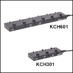
Multiple units can be mounted and connected to a single PC by using the KCH301 or KCH601 USB Controller Hubs. They each consist of two parts: the hub, which can support up to three (KCH301) or six (KCH601) K-Cubes or T-Cubes, and a power supply that plugs into a standard wall outlet. K-Cubes simply clip into place using the provided on-unit clips, while current- and previous-generation T-Cubes require the KAP101 Adapter Plate, shown in Video 4.2. The hub vastly reduces the number of USB and power cables required when operating multiple controllers.
K-Cube Table Mounting Plate
Kinesis USB Controller Hubs
Video 4.2 3- and 6-Port USB Controller Hubs allow multiple controllers to be connected to one PC for multi-axis applications. K-Cubes can be directly attached to the hubs while T-Cubes require a KAP101 Adapter Plate.
KINESIS SOFTWARE
Software
Kinesis Version 1.14.53
The Kinesis Software Package, which includes a GUI for control of Thorlabs' Kinesis system controllers.
Also Available:
- Communications Protocol
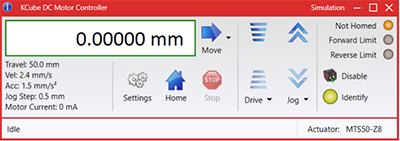
Figure 58A Kinesis GUI Screen
Thorlabs offers the Kinesis® software package to drive our wide range of motion controllers. The software can be used to control devices in the Kinesis family, which covers a wide variety of motion controllers ranging from small, low-powered, single-channel drivers (such as the K-Cubes®) to high-power, multi-channel benchtop units and modular 19" rack nanopositioning systems (the MMR60x Rack System).
The Kinesis Software features .NET controls which can be used by 3rd party developers working in the latest C#, Visual Basic, LabVIEW™, or any .NET compatible languages to create custom applications. Low-level DLL libraries are included for applications not expected to use the .NET framework and APIs are included with each install. A Central Sequence Manager supports integration and synchronization of all Thorlabs motion control hardware.
By providing this common software platform, Thorlabs has ensured that users can mix and match any of our motion control devices in a single application, while only having to learn a single set of software tools. In this way, it is perfectly feasible to combine any of the controllers from single-axis to multi-axis systems and control all from a single, PC-based unified software interface.
The software package allows two methods of usage: graphical user interface (GUI) utilities for direct interaction with and control of the controllers 'out of the box', and a set of programming interfaces that allow custom-integrated positioning and alignment solutions to be easily programmed in the development language of choice.
KINESIS TUTORIALS
Thorlabs' Kinesis® software features new .NET controls which can be used by third-party developers working in the latest C#, Visual Basic, LabVIEW™, or any .NET compatible languages to create custom applications.
C#
This programming language is designed to allow multiple programming paradigms, or languages, to be used, thus allowing for complex problems to be solved in an easy or efficient manner. It encompasses typing, imperative, declarative, functional, generic, object-oriented, and component-oriented programming. By providing functionality with this common software platform, Thorlabs has ensured that users can easily mix and match any of the Kinesis controllers in a single application, while only having to learn a single set of software tools. In this way, it is perfectly feasible to combine any of the controllers from the low-powered, single-axis to the high-powered, multi-axis systems and control all from a single, PC-based unified software interface.
The Kinesis System Software allows two methods of usage: graphical user interface (GUI) utilities for direct interaction and control of the controllers 'out of the box', and a set of programming interfaces that allow custom-integrated positioning and alignment solutions to be easily programmed in the development language of choice.
For a collection of example projects that can be compiled and run to demonstrate the different ways in which developers can build on the Kinesis motion control libraries, click on the links below. Please note that a separate integrated development environment (IDE) (e.g., Microsoft Visual Studio) will be required to execute the Quick Start examples. The C# example projects can be executed using the included .NET controls in the Kinesis software package (see the Kinesis Software tab for details).
 |
Click Here for the Kinesis with C# Quick Start Guide Click Here for C# Example Projects Click Here for Quick Start Device Control Examples |
|
LabVIEW
LabVIEW can be used to communicate with any Kinesis-based controller via .NET controls. In LabVIEW, you build a user interface, known as a front panel, with a set of tools and objects and then add code using graphical representations of functions to control the front panel objects. The LabVIEW tutorial, provided below, provides some information on using the .NET controls to create control GUIs for Kinesis-driven devices within LabVIEW. It includes an overview with basic information about using controllers in LabVIEW and explains the setup procedure that needs to be completed before using a LabVIEW GUI to operate a device.
 |
Click Here to View the LabVIEW Guide Click Here to View the Kinesis with LabVIEW Overview Page |
|
LASER SAFETY
Laser Safety and Classification
Safe practices and proper usage of safety equipment should be taken into consideration when operating lasers. The eye is susceptible to injury, even from very low levels of laser light. Thorlabs offers a range of laser safety accessories that can be used to reduce the risk of accidents or injuries. Laser emission in the visible and near infrared spectral ranges has the greatest potential for retinal injury, as the cornea and lens are transparent to those wavelengths, and the lens can focus the laser energy onto the retina.
 |
 |
 |
 |
 |
 |
 |
 |
 |
Safe Practices and Light Safety Accessories
- Laser safety eyewear must be worn whenever working with Class 3 or 4 lasers.
- Regardless of laser class, Thorlabs recommends the use of laser safety eyewear whenever working with laser beams with non-negligible powers, since metallic tools such as screwdrivers can accidentally redirect a beam.
- Laser goggles designed for specific wavelengths should be clearly available near laser setups to protect the wearer from unintentional laser reflections.
- Goggles are marked with the wavelength range over which protection is afforded and the minimum optical density within that range.
- Laser Safety Curtains and Laser Safety Fabric shield other parts of the lab from high energy lasers.
- Blackout Materials can prevent direct or reflected light from leaving the experimental setup area.
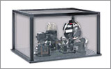
- Thorlabs' Enclosure Systems can be used to contain optical setups to isolate or minimize laser hazards.
- A fiber-pigtailed laser should always be turned off before connecting it to or disconnecting it from another fiber, especially when the laser is at power levels above 10 mW.
- All beams should be terminated at the edge of the table, and laboratory doors should be closed whenever a laser is in use.
- Do not place laser beams at eye level.
- Carry out experiments on an optical table such that all laser beams travel horizontally.
- Remove unnecessary reflective items such as reflective jewelry (e.g., rings, watches, etc.) while working near the beam path.
- Be aware that lenses and other optical devices may reflect a portion of the incident beam from the front or rear surface.
- Operate a laser at the minimum power necessary for any operation.
- If possible, reduce the output power of a laser during alignment procedures.
- Use beam shutters and filters to reduce the beam power.
- Post appropriate warning signs or labels near laser setups or rooms.
- Use a laser sign with a lightbox if operating Class 3R or 4 lasers (i.e., lasers requiring the use of a safety interlock).
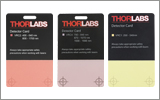
- Do not use Laser Viewing Cards in place of a proper Beam Trap.
Laser Classification
Lasers are categorized into different classes according to their ability to cause eye and other damage. The International Electrotechnical Commission (IEC) is a global organization that prepares and publishes international standards for all electrical, electronic, and related technologies. The IEC document 60825-1 outlines the safety of laser products. A description of each class of laser is given below:
| Class | Description | Warning Label |
|---|---|---|
| 1 | This class of laser is safe under all conditions of normal use, including use with optical instruments for intrabeam viewing. Lasers in this class do not emit radiation at levels that may cause injury during normal operation, and therefore the maximum permissible exposure (MPE) cannot be exceeded. Class 1 lasers can also include enclosed, high-power lasers where exposure to the radiation is not possible without opening or shutting down the laser. |  |
| 1M | Class 1M lasers are safe except when used in conjunction with optical components such as telescopes and microscopes. Lasers belonging to this class emit large-diameter or divergent beams, and the MPE cannot normally be exceeded unless focusing or imaging optics are used to narrow the beam. However, if the beam is refocused, the hazard may be increased and the class may be changed accordingly. |  |
| 2 | Class 2 lasers, which are limited to 1 mW of visible continuous-wave radiation, are safe because the blink reflex will limit the exposure in the eye to 0.25 seconds. This category only applies to visible radiation (400 - 700 nm). |  |
| 2M | Because of the blink reflex, this class of laser is classified as safe as long as the beam is not viewed through optical instruments. This laser class also applies to larger-diameter or diverging laser beams. |  |
| 3R | Class 3R lasers produce visible and invisible light that is hazardous under direct and specular-reflection viewing conditions. Eye injuries may occur if you directly view the beam, especially when using optical instruments. Lasers in this class are considered safe as long as they are handled with restricted beam viewing. The MPE can be exceeded with this class of laser; however, this presents a low risk level to injury. Visible, continuous-wave lasers in this class are limited to 5 mW of output power. |  |
| 3B | Class 3B lasers are hazardous to the eye if exposed directly. Diffuse reflections are usually not harmful, but may be when using higher-power Class 3B lasers. Safe handling of devices in this class includes wearing protective eyewear where direct viewing of the laser beam may occur. Lasers of this class must be equipped with a key switch and a safety interlock; moreover, laser safety signs should be used, such that the laser cannot be used without the safety light turning on. Laser products with power output near the upper range of Class 3B may also cause skin burns. |  |
| 4 | This class of laser may cause damage to the skin, and also to the eye, even from the viewing of diffuse reflections. These hazards may also apply to indirect or non-specular reflections of the beam, even from apparently matte surfaces. Great care must be taken when handling these lasers. They also represent a fire risk, because they may ignite combustible material. Class 4 lasers must be equipped with a key switch and a safety interlock. |  |
| All class 2 lasers (and higher) must display, in addition to the corresponding sign above, this triangular warning sign. |  |
|
K-Cube® Laser Sources

- FC/PC-Coupled Output
- 635 nm or 1550 nm Center Wavelength
- Top Panel Display Screen and Controls for Standalone Operation
- USB Connectivity for PC Operation with the Kinesis® Software
- Power Supply Not Included (See Below)
The KLS635 and KLS1550 K-Cube® laser sources are compact units with a fiber-coupled Fabry-Perot laser diode. The unit can be operated via the top panel display screen and controls as soon as the device is turned on. Alternatively, a USB connection allows for remote PC operation with the Kinesis software. An integrated feedback circuit maintains constant optical output power at the selected output intensity level.
The unit has a very small 121.0 mm x 60.0 mm x 47.0 mm (4.76" x 2.36" x 1.85") footprint and may be mounted directly to the optical table using the 1/4" (M6) counterbored slots in the base plate. This compact size allows the laser source to be positioned close to the rest of the system for added convenience when manually adjusting components. Tabletop operation also allows minimal cable lengths for easier cable management.
Please note that this controller does not ship with a power supply. Compatible power supplies are listed below.
Part Number | Description | Price | Availability |
|---|---|---|---|
KLS635 | K-Cube Laser Source, 635 nm, 8.0 mW Max (Power Supply Sold Separately) | $1,811.39 | Lead Time |
KLS1550 | K-Cube Laser Source, 1550 nm, 7.0 mW Max (Power Supply Sold Separately) | $1,586.10 | Lead Time |
Compatible Power Supplies

Click for Details
Figure 780B Each KPS201 power supply includes one region-specific adapter, which can be selected upon checkout.

Click to Enlarge
Figure 780A The KPS201 Power Supply Unit
- Individual Power Supply
- KPS201: For K-Cubes® or T-Cubes™ with 3.5 mm Jacks
- USB Controller Hubs Provide Power and Communications
- KCH301: For Up to Three K-Cubes or T-Cubes
- KCH601: For Up to Six K-Cubes or T-Cubes
The KPS201 power supply outputs +15 VDC at up to 2.66 A and can power a single K-Cube or T-Cube with a 3.5 mm jack. It plugs into a standard wall outlet.
The KCH301 and KCH601 USB Controller Hubs each consist of two parts: the hub, which can support up to three (KCH301) or six (KCH601) K-Cubes or T-Cubes, and a power supply that plugs into a standard wall outlet. The hub draws a maximum current of 10 A; please verify that the cubes being used do not require a total current of more than 10 A. In addition, the hub provides USB connectivity to any docked K-Cube or T-Cube through a single USB connection.
For more information on the USB Controller Hubs, see the full web presentation.
Part Number | Description | Price | Availability |
|---|---|---|---|
KPS201 | 15 V, 2.66 A Power Supply Unit with 3.5 mm Jack Connector for One K- or T-Cube | $43.15 | Today |
KCH301 | USB Controller Hub and Power Supply for Three K-Cubes or T-Cubes | $640.53 | Lead Time |
KCH601 | USB Controller Hub and Power Supply for Six K-Cubes or T-Cubes | $775.24 | Lead Time |