
T-Cube™ LED Driver

- LED Current Up to 1200 mA
- Modulation Up to 5 kHz
- Trigger Mode Up to 1 kHz
- Adjustable LED Current Limit
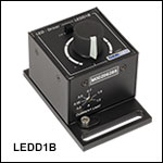
LEDD1B
Power Supply
Sold Separately
Application Idea
Multiple High-Power LEDs
and Drivers Being Used
in the Same Application
OVERVIEW
| LED Controller Selection Guide | ||||||
|---|---|---|---|---|---|---|
| Type | Max Number of LEDs |
Max Current |
Modulation Mode |
USB | Remote Operation | Compatible LEDs |
| upLED™ LED Driver |
1 | 1.2 A | - | Yes | Yes | Mounted, Collimated, Fiber Coupled, Diffuse Backlight, and PCB Mounteda |
| Compact T-Cube Driver |
1 | 1.2 A | 0 - 5 kHz | No | No | |
| 4-Channel Driver |
4 | 1 A | 0 - 100 kHz | Yes | Yes | |
| 4.0 A LED Driver | 1 | 4.0 A | 0 - 5 kHz | Yes | Yes | |
| Solis® LED Driver |
1 | 10 A | 0 - 1 kHz | No | No | High Power |
| High-Power Touchscreen Driver |
1 | 10.0 A | 0 - 250 kHz | Yes | Yes | High Power, Mounted, Collimated, Fiber Coupled, Diffuse Backlight, and PCB Mounteda |

Click to Enlarge
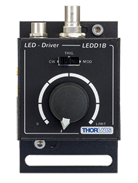
Back View of the LEDD1B T-Cube. For more information, please see the Pin Diagrams tab.
Click to Enlarge
Top View of the LEDD1B T-Cube
| Compact Light Source & Driver Modules |
|---|
| Laser Sources |
| Laser Diode Driver |
| LED Driver |

Current Limit Adjuster
Features
- Easy-to-Use LED Driver
- 3 Operation Modes:
- Constant Current Mode
- Modulation Mode
- Trigger Mode
- Compact Footprint Measuring: 60 mm x 60 mm x 47 mm (2.4" x 2.4" x 1.8")
- Pulse Width and Frequency Control via External 0 - 5 V Signal
- Adjustable LED Current Limit
- Includes One CAB-LEDD1 Cable (Additional Cables Available Separately Below)
The LEDD1B driver is designed to drive high-power LEDs with currents up to 1200 mA. It features an adjustable LED current limit to protect the connected LED. The output current limit can be adjusted continuously from 0.2 A to 1.2 A using the key slot on the front of the unit (shown below and to the right), thereby ensuring the output current does not exceed the limit regardless of the other settings or the modulation input voltage.
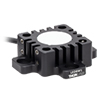
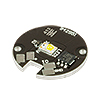
The LEDD1B driver is compatible with our collimated, uncollimated, PCB-mounted, diffuse backlight, and fiber-coupled LEDs, as well as with select unmounted LEDs offered by Thorlabs for which the maximum forward DC current is higher than 200 mA. When driving these LEDs, care must be taken to ensure the LEDD1B current limit is set at or below the LED's maximum forward DC current rating. Set the current limit (see below and to the right) by rotating the arrow direction with a flathead screwdriver (one flathead screwdriver is included with each LEDD1B).
The LEDD1B driver offers three operation modes:
- Constant Current Mode: The output current is set between 0 mA and 1200 mA using the knob on the top of the unit. The range of output current controlled by the knob on the top of the unit will rescale to a maximum value set by the current limit.
- Modulation Mode: The output current exactly follows the amplitude and waveform of the voltage input signal, independent of the knob setting on the top of the T-Cube control unit.
- Trigger Mode: The output current switches to the level that has been selected by the knob on the top of the unit as soon as an input voltage threshold is reached. The voltage threshold is fixed and cannot be changed by the user. This mode can be used for pulse width modulation (PWM).
The operation mode can be changed by a switch next to the current selector knob. The trigger and modulation modes are controlled by an external voltage in the 0 to 5 V range.
This LED Driver has the same compact form factor as other T-Cube modules. It is shipped attached to a removable base plate, which allows the T-Cube to be easily secured to an optical table.
Multi-LED Source
A customizable multi-LED source can be constructed using our mounted high-power LEDs and other Thorlabs items. This source may be configured for integration with Thorlabs' flexible SM1 Lens Tube Systems, 30 mm Cage Systems, and microscope adapters. Please see the Multi-LED Source tab for a detailed item list and instructions. Thorlabs also offers integrated, user-configurable 4-Wavelength LED Sources that can be driven using our four-channel LED drivers.
Warning!
The LEDD1B is designed for high-brightness LEDs only. The LED current limit must be adjusted by the trim pot on the front of the unit so that the maximum current of the connected LED will not be exceeded. The available range for this limit is 200 to 1200 mA.
Power Supply Options
The preferred power supply (single channel or hub-based) depends on the end user's application and whether you already own compatible power supplies. To that end and in keeping with Thorlabs' green initiative, we do not ship these units bundled with a power supply. This avoids the cost and inconvenience of receiving an unwanted single-channel supply if a hub-based system would be more appropriate. The power supply options compatible with the LEDD1B LED Driver are listed below.
| Compatible Thorlabs LEDs | |||||
|---|---|---|---|---|---|
| Photo (Click for Link) |
 |
 |
 |
 |
 |
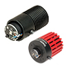
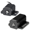
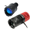
| LED Description | Mounted | Fiber Coupled | Collimated | Diffuse Backlight | PCB Mounteda |
SPECS
| Specification | Value |
|---|---|
| Common Data | |
| Output Current Range | 0 - 1200 mA |
| LED Current Limit Set Point Range | 200 - 1200 mA |
| LED Forward Voltage | 11 V (Min) 12 V (Typical) |
| Current Ripple | 8 mA |
| Current Ripple Frequency | 570 kHz |
| Modulation Modea,b | |
| Frequency Range | 0 - 5 kHz, Sine Wave |
| Modulation Form | Arbitrary |
| Input Voltage Rate | 0 - 5 V |
| Slew Rate | 13.6 mA/µs |
| Decay Rate | 13.1 mA/µs |
| Trigger Modea | |
| Frequency Range | 0 - 1 kHz |
| Duty Cycle Range | 20 - 80% @ 1 kHz 2 - 98% @ 100 Hz 0.2 - 99.8% @ 10 Hz |
| Modulation Form | Square Wave / PWM |
| Logic Input Levels | TTL Min H-Level: 2 V Max L-Level: 0.55 V |
| Slew Rate | 18 mA/µs |
| Rise Time | 51 µs |
| Decay Rate | 12 mA/µs |
| Fall Time | 79 µs |
| General Data | |
| Power Supply | 15 VDC |
| Maximum Power Consumption | 15 VA |
| Operating Temperature | 0 - 40 °C |
| Storage Temperature | -40 to 70 °C |
| Weight | 240 g |
| Dimensions (W x H x D) | 60 mm x 73 mm x 104 mm |
PIN DIAGRAMS
Modulation In
BNC Female
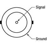
0 to 5 V external LED control.
LED Connector - Female

| Pin | Description |
|---|---|
| 1 | LED Anode |
| 2 | LED Cathode |
| 3 | Unused |
| 4 | Unused |
MOUNTING OPTIONS
T-Cube Mounting Options
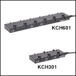
Two options are available to securely mount our T-Cube controllers onto an optical table. An optical table mounting plate, provided with every T-Cube, allows for a single controller to be attached to an optical table. Alternatively, multiple units can be mounted and connected to a single PC by using the KCH301 or KCH601 USB Controller Hubs. They each consist of two parts: the hub, which can support up to three (KCH301) or six (KCH601) T-Cubes or K-Cubes, and a power supply that plugs into a standard wall outlet. Current- and previous-generation T-Cubes require the previously mentioned mounting plate to be removed and replaced with the KAP101 Adapter Plate, shown in the animation below.
T-Cube and K-Cube Mounting On USB Controller Hubs
3- and 6-Port USB Controller Hubs allow multiple controllers to be connected to one PC for multi-axis applications. K-Cubes can be directly attached to the hubs while T-Cubes require a KAP101 Adapter Plate.
MULTI-LED SOURCE

Click to Enlarge
Multi-LED Source Coupled to Microscope Illumination Port
Creating a Custom Multi-LED Source for Microscope Illumination
Thorlabs offers the items necessary to create your own custom multi-LED light source using two or three of the mounted LEDs offered below. As configured in the following example, the light source is intended to be used with the illumination port of a microscope. However, it may be integrated with other applications using Thorlabs' versatile SM1 Lens Tube and 30 mm Cage Systems. Thorlabs also offers integrated, user-configurable 4-Wavelength LED Sources.
Design & Construction
First, light will be collimated by lenses mounted in lens tubes. Dichroic mirrors mounted in kinematic cage cubes then combine the output from the multiple LEDs. The mounted LEDs may be driven by LEDD1B Compact T-Cube LED Drivers (power supplies are sold separately). The LEDD1B LED Drivers allow each LED's output to be independently modulated and can provide up to 1200 mA of current. Please take care not to drive the LED sources above their max current ratings.
When designing your custom source, select mounted LEDs from below along with dichroic mirror(s) that have cutoff wavelength(s) between the LED wavelengths. The appropriate dichroic mirror(s) will reflect light from side-mounted LEDs and transmit light along the optical axis. Please note that most of these dichroic mirrors are "longpass" filters, meaning they transmit the longer wavelengths and reflect the shorter wavelengths. To superimpose light from three or more LEDs, add each in series (as shown below), starting from the back with longer wavelength LEDs when using longpass filters. Shortpass filters may also used if the longer wavelength is reflected and the shorter wavelength is transmitted. Sample combinations of compatible dichroic mirrors and LEDs are offered in the three tables below.
It is also necessary to select an aspheric condenser lens for each source with AR coatings appropriate for the source. Before assembling the light source, collimate the light from each mounted LED as detailed in the Collimation tab. For mounting the aspheric lenses in the SM1V05 Lens Tubes using the included SM1RR retaining rings, we recommend the SPW801 Adjustable Spanner Wrench. A properly collimated LED source should have a resultant beam that is approximately homogenous and not highly divergent at a distance of approximately 2 feet (60 cm). An example of a well-collimated beam is shown on the Collimation tab.
After each LED source is collimated, thread the SM1V05 Lens Tubes at the end of each collimated LED assembly into their respective C4W Cage Cube ports using SM1T2 Lens Tube Couplers. Install each dichroic filter in an FFM1 Dichroic Filter Holder, and mount each filter holder onto a B4C Kinematic Cage Cube Platform. Each platform is then installed in the C4W Cage Cubes by partially threading the included screws into the bottom of the cube, and then inserting and rotating the B4C platform into place. Align the platform to the desired position and then firmly tighten the screws. To connect multiple cage cubes and the microscope adapter, use the remaining SM1T2 lens tube couplers along with an SM1L05 0.5" Lens Tube between adjacent cage cubes. Finally, adjust the rotation, tip, and tilt of each B4C platform to align the reflected and transmitted beams so they overlap as closely as possible.
If desired, a multi-LED source may be constructed that employs more than three LEDs. The limiting factors for the number of LEDs that can be practically used are the collimation of the light and the dichroic mirror efficiency over the specified range. Heavier multi-LED sources may be supported with our Ø1" or Ø1.5" Posts.

Click to Enlarge
Three-LED Source Using Components Mounted LEDs and Dichroic Mirrors
Detailed in Example Configuration 1
| Parts List | |||||
|---|---|---|---|---|---|
| # | Product Description | Item # | 2 LEDs | 3 LEDs | |
| Item Qty. | |||||
| 1 | Microscope Illumination Port Adapter: |
Olympus IX or BX | SM1A14 | 1 | 1 |
| Leica DMI | SM1A21 | ||||
| Zeiss Axioskop | SM1A23a | ||||
| Nikon Eclipse Ti | SM1A26 | ||||
| 2 | Mounted LEDb | - | 2 | 3 | |
| - | T-Cube LED Driver, 1200 mA Max Drive Current | LEDD1Bc | 2 | 3 | |
| - | 15 V Power Supply Unit for T-Cube | KPS201c | 2 | 3 | |
| 3 | 4-Way Mounting 30 mm Cage Cube | C4W | 1 | 2 | |
| 4 | Kinematic Cage Cube Platform for C4W/C6W | B4C | 1 | 2 | |
| 5 | 30 mm Cage-Compatible Dichroic Filter Mount | FFM1 | 1 | 2 | |
| 6 | Dichroic Filter(s)d | - | 1 | 2 | |
| 7 | Externally SM1-Threaded End Cap | SM1CP2 | 1 | 2 | |
| 8 | SM1 (1.035"-40) Coupler, External Threads, 0.5" Long | SM1T2 | 3 | 5 | |
| 9 | Ø1" SM1 Lens Tube, 1/2" Long External Threads | SM1V05 | 2 | 3 | |
| - | Aspheric Condenser Lens |
AR-Coated 350 - 700 nm | ACL2520U-Ac,e | 2 | 3 |
| AR-Coated 650 - 1050 nm | ACL2520U-Bc,e | ||||
| 10 | SM1 Lens Tube, 0.3" Thread Depth | SM1L03 | 2 | 4 | |
| - | Blank Cover Plate with Rubber O-Ring for C4W/C6W | B1Cc | 1 | 2 | |
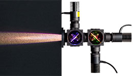
Click to Enlarge
Beam Profile of Source with 3 Mounted LEDs

Click to Enlarge
Two-LED source. This is the same as Example 1, but with the blue LED removed.
T-Cube™ LED Driver with Trigger Mode, 1200 mA Max (Power Supply Not Included)
Click to Enlarge
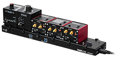
KCH601 USB Controller Hub with Installed T-Cube and K-Cube™ Modules
The compact LEDD1B T-Cube is capable of driving high-brightness LEDs with currents up to 1200 mA. The output power can be varied using the manual control knob and modulated using an external trigger signal; the maximum output current is set using an adjuster on the front of the T-Cube. One flathead screwdriver to adjust the current limit and one CAB-LEDD1 connection cable are included with each LEDD1B.
Please note that unlike our other T- and K-Cube modules, the LEDD1B LED Driver is fully manual. This T-Cube lacks USB connectivity and cannot be controlled via the Kinesis® software.
Power supplies are sold separately; please see the options below.
Part Number | Description | Price | Availability |
|---|---|---|---|
LEDD1B | T-Cube LED Driver, 1200 mA Max Drive Current (Power Supply Not Included) | $355.18 | 3-5 Days |
Compatible Power Supplies
Click for Details
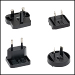
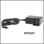
Each KPS201 power supply includes one region-specific adapter, which can be selected upon checkout.
Click to Enlarge
The KPS201 Power Supply Unit
- Power Supplies
- KPS201: For K-Cubes™ or T-Cubes™ with 3.5 mm Jacks
- USB Controller Hubs Provide Power and Communications
- KCH301: For up to Three K-Cubes or T-Cubes
- KCH601: For up to Six K-Cubes or T-Cubes
- KAP101: Adapter Plate for Connecting 60 mm Wide T-Cubes to KCH Hubs
- KAP102: Adapter Plate for Connecting 120 mm Wide T-Cubes to KCH Hubs
The KPS201 can supply up to 2.66 A and power a single K-Cube or T-Cube. It plugs into a standard wall outlet and provides +15 VDC.
The KCH301 and KCH601 USB Controller Hubs each consist of two parts: the hub, which can support up to three (KCH301) or six (KCH601) K-Cubes or T-Cubes, and a power supply that plugs into a standard wall outlet. The hub draws a maximum current of 10 A; please verify that the cubes being used do not require a total current of more than 10 A. In addition, the hub provides USB connectivity to any docked K-Cube or T-Cube through a single USB connection. Note that the LEDD1B LED Driver does not include USB connectivity and cannot be controlled through the Kinesis® software.
A KAP101 or KAP102 Adapter Plate (sold separately) is required for each T-Cube to operate on the KCH301 or KCH601 controller hub. The KAP101 is designed to adapt 60 mm wide T-Cubes to the hubs, while the KAP102 is designed to adapt 120 mm wide T-Cubes to the hubs. Please see the Mounting Options tab for more details.
For more information on the USB Controller Hubs, see the full web presentation.
Part Number | Description | Price | Availability |
|---|---|---|---|
KPS201 | 15 V, 2.66 A Power Supply Unit with 3.5 mm Jack Connector for One K- or T-Cube | $40.33 | 3-5 Days |
KCH301 | USB Controller Hub and Power Supply for Three K-Cubes or T-Cubes | $598.63 | 3 Weeks |
KCH601 | USB Controller Hub and Power Supply for Six K-Cubes or T-Cubes | $724.52 | 3 Weeks |
KAP101 | Adapter Plate for KCH Series Hubs and 60 mm Wide T-Cubes | $69.43 | 3 Weeks |
KAP102 | Adapter Plate for KCH Series Hubs and 120 mm Wide T-Cubes | $75.60 | 3-5 Days |
LED Connection Cable
 Male M8x1 Connector |
Pin | Description | Wire Color |
|---|---|---|---|
| 1 | LED Anode | Brown | |
| 2 | LED Cathode | White | |
| 3 | EEPROM GND | Black | |
| 4 | EEPROM IO | Blue |
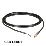
- 4-Pin M8 Connector on One Side
- 4 Bare Wires on Other Side
- 2 m Long, 24 AWG Wires
The 4-Pin M8 connection cable can be used to connect the high-power LEDs on metal core PCB or other custom LEDs to the following Thorlabs LED drivers: LEDD1B, DC40, DC2200, DC4100, and DC4104 (the latter two require the DC4100-HUB).
Pin Connection - Male
The diagram above shows the male connector for use with the above Thorlabs LED drivers. The connector is a standard M8x1 sensor circular connector. Pins 1 and 2 are the connection to the LED. If using this cable with a non-Thorlabs LED, do not connect anything to the black and blue wires, as this can damage the LED driver. Please note that the pin connection diagram shown here may not be valid for third-party LED drivers.
Part Number | Description | Price | Availability |
|---|---|---|---|
CAB-LEDD1 | LED Connection Cable, 2 m, M8 Connector, 4 Wires | $18.89 | 3-5 Days |

