

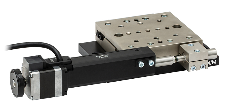
100 mm Linear Translation Stage, Stepper Motor

- Stackable in XY, XZ, and XYZ Configurations
- Typical Calibrated On-Axis Accuracy of 2.0 µm
- Horizontal Load Capacity of 20 kg (44 lbs)
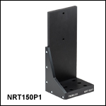
NRT150P1
Right-Angle Bracket
NRT100
100 mm Translation Stage
Application Idea
Two NRT100 Stages
in XZ Configuration,
Using an NRT150P1
Right-Angle Bracket
OVERVIEW
| Key Specificationsa | |
|---|---|
| Travel Range | 100 mm (3.9") |
| Velocity (Max)b | 30 mm/s |
| Minimum Achievable Incremental Movement | 0.1 µm |
| On-Axis Accuracyc | 2.0 µm (Typical) 5.0 µm (Max) |
| Bidirectional Repeatabilityd | 1 µm |
| Backlashe | <3 µm |
| Horizontal Load Capacity (Max) | 20 kg (44 lbs) |
| Vertical Load Capacity (Max) | 5 kg (11 lbs) |
| Actuator Type | Stepper Motor |
| Cable Length | 3.0 m (9.8 ft) |
| Recommended Controller | Benchtop Stepper Motor Controllers |
| Motorized Linear Translation Stages | |
|---|---|
| 100 mm | Stepper |
| DC Servo | |
| 150 mm | Stepper |
| Stepper with Integrated Controller | |
| 220 mm | DC Servo |
| 300 mm | Stepper with Integrated Controller |
| DC Servo | |
| 600 mm | DC Servo |
| Optical Delay Line Kits | |
| Other Translation Stages | |
Features
- 100 mm Travel Range
- Load Capacity
- Horizontal: 20 kg (44 lbs)
- Vertical: 5 kg (11 lbs)
- Maximum Velocity of 30 mm/s
- Bidirectional Repeatability of 1 µm
- XY, XZ, and XYZ Configurable
- 1/4"-20 (M6) Tapped Holes for Mounting Standard Optomechanics
Thorlabs' NRT100(/M) Linear Positioning Stage is optimized for applications requiring high load capacity and high resolution, such as measurement and inspection. It provides 100 mm of linear travel for loads as great as 20 kg (44 lbs) when mounted horizontally and 5 kg (11 lbs) when mounted vertically. Each stage features a typical on-axis accuracy of 2.0 µm (5.0 µm Max) when the included calibration files are used with Thorlabs' Kinesis® software. The lead screw, directly driven by a two-phase stepper motor with
409 600 microsteps per revolution, provides smooth translation with a theoretical positional resolution of less than 100 nm. Due to the stepper motor design, the platform position remains fixed when no power is supplied to the stage, unlike with DC servo motor translation stages.
The main platform is supported by four recirculating ball carrier bearings mounted to precisely aligned linear guide rails. The stepper motor, specifically designed for microstepping applications, allows smaller and smoother low-speed motion with significantly reduced vibrational noise than DC servo motors. The choice of a trapezoidal lead screw provides a number of benefits over the more common Acme-style thread, including improved durability, lower friction due to improved surface quality, and very little backdrive, eliminating the need for the braking mechanism required with ball screws.
Calibration Files
Each NRT100(/M) Linear Translation Stage is calibrated during manufacturing. Calibration enables the controller to correct for any mechanical errors present in the system. Mechanical components, such as the lead screw and linkages, can be machined only within a certain tolerance. These mechanical errors result in deviations of the actual position from the commanded position. However, the deviations are repeatable and can be compensated for using the Kinesis software and included calibration files, which convert the position entered by the user into the required mechanical motion. The calibration files can be downloaded by clicking on the red Docs icon  )
)
The use of calibration files is optional. Without installing a calibration file, the on-axis accuracy of a stage will fall from 2.0 µm (typical) to 15.29 µm (typical). Calibration files do not affect the repeatability and resolution of the stages.
Stage Combinations
If an XY configuration is desired, any combination of NRT100 and NRT150 Linear Positioning Stages (the latter features a 150 mm travel range) can be mounted directly atop one another by using 1/4"-20 (M6) cap screws together with the provided counterbored holes and slots. These counterbores are accessed through the Ø0.59" (Ø15.0 mm) clearance hole in the moving carriage. XZ and XYZ configurations are possible using our NRT150P1(/M) Vertical Mounting Bracket, which orients either an NRT100 or NRT150 in the vertical plane.
Controller Options
One of Thorlabs' benchtop stepper motor controllers, available in one-, two-, or three-channel versions, is required to drive this 100 mm translation stage. These controllers are compatible with the Kinesis software, which provides out-of-the-box stage control from a PC and enables support for common programming interfaces like LabVIEW and LabWindows™.
One PAA613 Motor Drive Cable is included with each of our NRT Series Translation Stages. Replacement cables are available below in case of loss or damage to the included cable.
SPECS
| Item # | NRT100(/M) |
|---|---|
| Translation | |
| Travel Range | 100 mm (3.9") |
| Bidirectional Repeatabilitya | 1 µm |
| Backlashb | <3 µm |
| Maximum Velocityc | 30 mm/s |
| Velocity Stability | ±0.1 mm/s |
| Maximum Accelerationc | 30 mm/s2 |
| Minimum Achievable Incremental Movementd | 0.10 µm |
| Minimum Repeatable Incremental Movemente | 2 µm |
| Accuracy | |
| Calibrated Absolute On-Axis Accuracy | 2.0 µm (Typical) 5.0 µm (Max) |
| Maximum Percentage Accuracyf | 0.09% |
| Home Location Accuracy | ±0.6 µm |
| Pitch | <0.008° (140 µrad) |
| Yaw | <0.05° (873 µrad) |
| Load Capacity | |
| Horizontal Load Capacity | <12 kg (26 lbs) (Recommended) 20 kg (44 lbs) (Max) |
| Vertical Load Capacity | <4 kg (9 lbs) (Recommended) 5 kg (11 lbs) (Max) |
| General | |
| Weight | 2.2 kg (4.9 lbs) |
| Dimensions | 362.7 mm x 100.0 mm x 43.5 mm (14.28" x 3.94" x 1.71") |
PIN DIAGRAM
PAA612 and PAA613 Stepper Motor Cables
DA15-Pin Male D-Type to DE15-Pin Female D-Type

| DA15 Male Pin | DE15 Female Pin | Description |
|---|---|---|
| 11 and 12 | 1 | Limit Switch Ground |
| 10 | 2 | Forward Limit Switch |
| 9 | 3 | Reverse Limit Switch |
| 7 | 4 | Motor Phase B -ve |
| 14 | 5 | Motor Phase B +ve |
| 8 | 6 | Motor Phase A -ve |
| 15 | 7 | Motor Phase A +ve |
| 6 | 9 | Not Connected |
| 5 | 13 | Limit Switch +5 V |
Motor Pin Out
D-Type Male

| Pin | Designation | Pin | Designation |
|---|---|---|---|
| 1 | Limit Switch Ground | 9 | Not Connected |
| 2 | Forward Limit Switch | 10 | Not Connected |
| 3 | Reverse Limit Switch | 11 | Not Connected |
| 4 | Motor Phase B -ve | 12 | Not Connected |
| 5 | Motor Phase B +ve | 13 | Limit Switch +5 V |
| 6 | Motor Phase A -ve | 14 | Not Connected |
| 7 | Motor Phase A +ve | 15 | Ground/Earth |
| 8 | Not Connected |
KINESIS SOFTWARE
Software
Kinesis Version 1.14.52
The Kinesis Software Package, which includes a GUI for control of Thorlabs' Kinesis system controllers.
Also Available:
- Communications Protocol
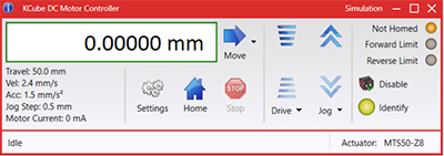
Figure 58A Kinesis GUI Screen
Thorlabs offers the Kinesis® software package to drive our wide range of motion controllers. The software can be used to control devices in the Kinesis family, which covers a wide variety of motion controllers ranging from small, low-powered, single-channel drivers (such as the K-Cubes®) to high-power, multi-channel benchtop units and modular 19" rack nanopositioning systems (the MMR60x Rack System).
The Kinesis Software features .NET controls which can be used by 3rd party developers working in the latest C#, Visual Basic, LabVIEW™, or any .NET compatible languages to create custom applications. Low-level DLL libraries are included for applications not expected to use the .NET framework and APIs are included with each install. A Central Sequence Manager supports integration and synchronization of all Thorlabs motion control hardware.
By providing this common software platform, Thorlabs has ensured that users can mix and match any of our motion control devices in a single application, while only having to learn a single set of software tools. In this way, it is perfectly feasible to combine any of the controllers from single-axis to multi-axis systems and control all from a single, PC-based unified software interface.
The software package allows two methods of usage: graphical user interface (GUI) utilities for direct interaction with and control of the controllers 'out of the box', and a set of programming interfaces that allow custom-integrated positioning and alignment solutions to be easily programmed in the development language of choice.
KINESIS TUTORIALS
Thorlabs' Kinesis® software features new .NET controls which can be used by third-party developers working in the latest C#, Visual Basic, LabVIEW™, or any .NET compatible languages to create custom applications.
C#
This programming language is designed to allow multiple programming paradigms, or languages, to be used, thus allowing for complex problems to be solved in an easy or efficient manner. It encompasses typing, imperative, declarative, functional, generic, object-oriented, and component-oriented programming. By providing functionality with this common software platform, Thorlabs has ensured that users can easily mix and match any of the Kinesis controllers in a single application, while only having to learn a single set of software tools. In this way, it is perfectly feasible to combine any of the controllers from the low-powered, single-axis to the high-powered, multi-axis systems and control all from a single, PC-based unified software interface.
The Kinesis System Software allows two methods of usage: graphical user interface (GUI) utilities for direct interaction and control of the controllers 'out of the box', and a set of programming interfaces that allow custom-integrated positioning and alignment solutions to be easily programmed in the development language of choice.
For a collection of example projects that can be compiled and run to demonstrate the different ways in which developers can build on the Kinesis motion control libraries, click on the links below. Please note that a separate integrated development environment (IDE) (e.g., Microsoft Visual Studio) will be required to execute the Quick Start examples. The C# example projects can be executed using the included .NET controls in the Kinesis software package (see the Kinesis Software tab for details).
 |
Click Here for the Kinesis with C# Quick Start Guide Click Here for C# Example Projects Click Here for Quick Start Device Control Examples |
|
LabVIEW
LabVIEW can be used to communicate with any Kinesis-based controller via .NET controls. In LabVIEW, you build a user interface, known as a front panel, with a set of tools and objects and then add code using graphical representations of functions to control the front panel objects. The LabVIEW tutorial, provided below, provides some information on using the .NET controls to create control GUIs for Kinesis-driven devices within LabVIEW. It includes an overview with basic information about using controllers in LabVIEW and explains the setup procedure that needs to be completed before using a LabVIEW GUI to operate a device.
 |
Click Here to View the LabVIEW Guide Click Here to View the Kinesis with LabVIEW Overview Page |
|
MOTORIZED LINEAR STAGES
Motorized Linear Translation Stages
Thorlabs' motorized linear translation stages are offered in a range of maximum travel distances, from a stage with 20 µm of piezo translation to our 600 mm direct drive stage. Many of these stages can be assembled in multi-axis configurations, providing XY or XYZ translation. For fiber coupling applications, please see our multi-axis stages, which offer finer adjustment than our standard motorized translation stages. In addition to motorized linear translation stages, we offer motorized rotation stages and goniometers. We also offer manual translation stages.
Piezo Stages
These stages incorporate piezoelectric elements in a variety of drive mechanisms. ORIC® stages incorporate piezo inertia drives that use "stick-slip" friction properties to obtain extended travel ranges. Our modular, quick-connect XRN25X and XR25X translation stages can be driven by the PIA25 piezo inertia actuator which operates using the same principle. Our Nanoflex™ translation stages use standard piezo chips along with manual actuators. Elliptec® stages use resonant piezo motors to push and pull the moving platform through resonant elliptical motion. Our LPS710E z-axis stage features a mechanically amplified piezo design and includes a matched controller.
| Piezoelectric Stages | |||||
|---|---|---|---|---|---|
| Product Family | ORIC® PDXZ1 Closed-Loop 4.5 mm Vertical Stage |
ORIC® PD2 Open-Loop 5 mm Stage |
ORIC® PDX2 Closed-Loop 5 mm Stage |
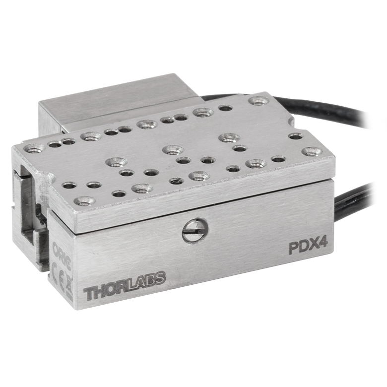
ORIC® PDX4 Closed-Loop 12 mm Stage |
|
| Click Photo to Enlarge |
 |
 |
 |
 |
|
| Travel | 4.5 mm | 5 mm | 12 mm | ||
| Speed | 1 mm/s (Typ.)a | 10 mm/s (Typ. Max)b | 8 mm/s (Typ.)c | 15 mm/s (Typ.)a | |
| Drive Type | Piezoelectric Inertia Drive | ||||
| Possible Axis Configurations | Z | X, XY, XYZ | |||
| Mounting Surface Size | 45.0 mm x 42.0 mm | 13.0 mm x 13.0 mm | 13.0 mm x 23.0 mm | ||
| Additional Details | |||||
| Piezoelectric Stages | |||||||
|---|---|---|---|---|---|---|---|
| Product Family | ORIC® PD1 Open-Loop 20 mm Stage |
ORIC® PD1D Open-Loop 20 mm Monolithic XY Stage |
ORIC® PDX1 Closed-Loop 20 mm Stage |
ORIC® PD3 Open-Loop 50 mm Stage |
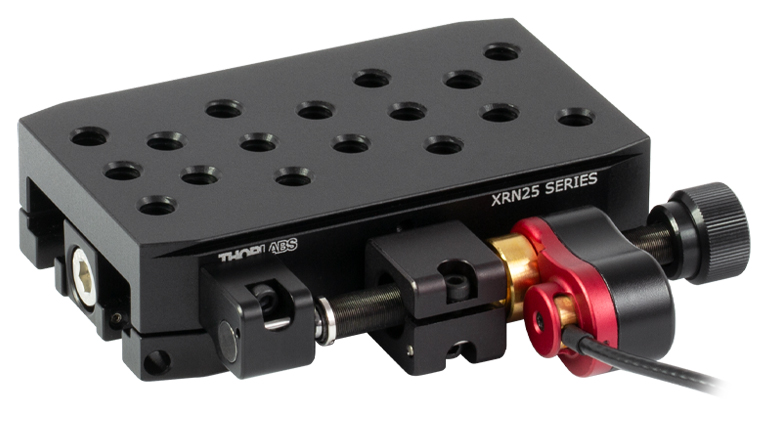
Compact Modular XRN25X 25 mm Stage |
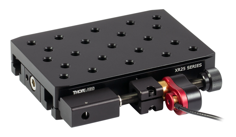
Modular XR25X 25 mm Stage |
|
| Click Photo to Enlarge |
 |
 |
 |
 |
 |
 |
|
| Travel | 20 mm | 50 mm | 25 mm | ||||
| Speed | 3 mm/s (Typ. Max)a | 20 mm/s (Typ. Max)b | 10 mm/sc | ≤3.6 mm/mind | ≤3.6 mm/mind | ||
| Drive Type | Piezoelectric Inertia Drive | ||||||
| Possible Axis Configurations | X, XY, XYZ | XY, XYZ | X, XY, XYZ | X, XY, XYZ | X, XY, YZ, XZ, XYZ | ||
| Mounting Surface Size | 30.0 mm x 30.0 mm | 80.0 mm x 30.0 mm | 85.0 mm x 50.7 mm | 110.0 mm x 75.7 mm | |||
| Additional Details | |||||||
| Piezoelectric Stages | ||||||
|---|---|---|---|---|---|---|
| Product Family | Nanoflex™ 20 µm Stage with 5 mm Actuator |
Nanoflex™ 25 µm Stage with 1.5 mm Actuator |
Elliptec® 28 mm Stage | Elliptec® 60 mm Stage | LPS710E 1.1 mm Vertical Stage | |
| Click Photo to Enlarge |
 |
 |
 |
 |
 |
|
| Travel | 20 µm + 5 mm Manual | 25 µm + 1.5 mm Manual | 28.0 mm | 60.0 mm | 1.1 mm | |
| Speed | - | 180 mm/s (Max) | 90 mm/s (Max) | - | ||
| Drive Type | Piezo with Manual Actuator | Resonant Piezoelectric Motor | Amplified Piezo | |||
| Possible Axis Configurations | X, XY, XYZ | X | Z | |||
| Mounting Surface Size | 75.0 mm x 75.0 mm | 30.0 mm x 30.0 mm | 15.0 mm x 15.0 mm | 21.0 mm x 21.0 mm | ||
| Additional Details | ||||||
Stepper Motor Stages
These translation stages feature removable or integrated stepper motors and long travel ranges up to 300 mm. Many of these stages either have integrated multi-axis capability (PLSXY) or can be assembled into multi-axis configurations (PLSX, Quick-Connect XRN25X and XR25X, LNR Series, NRT Series, and LTS Series stages). The MLJ150 stage also offers high load capacity vertical translation.
| Stepper Motor Stages | |||||||
|---|---|---|---|---|---|---|---|
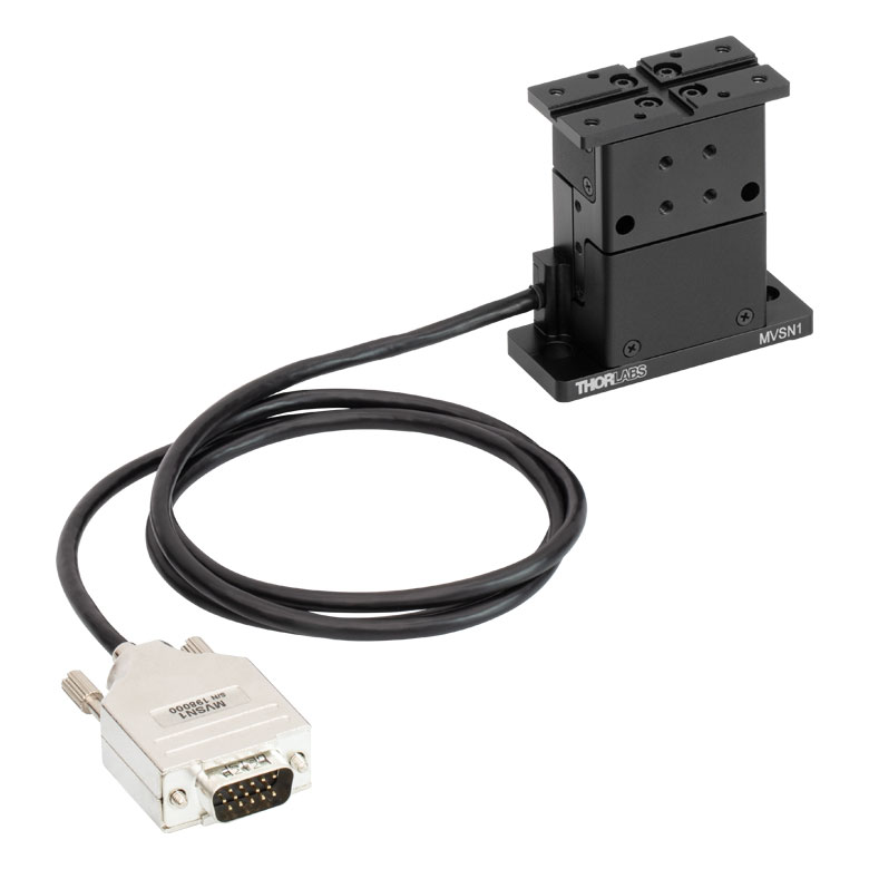
| Product Family | MVSN1(/M) 13 mm Vertical Stage |
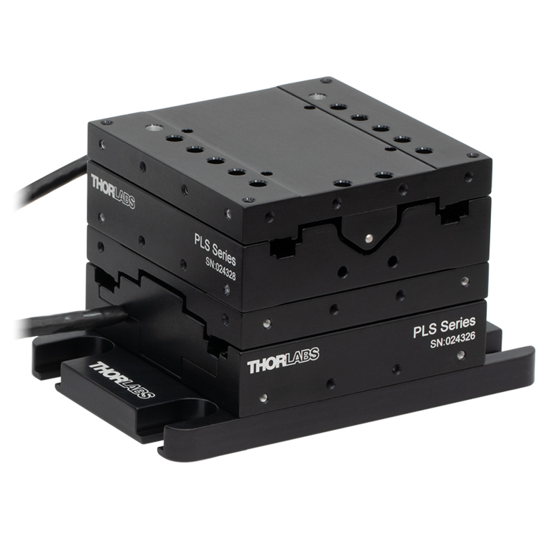
PLS Series 1" Stages |
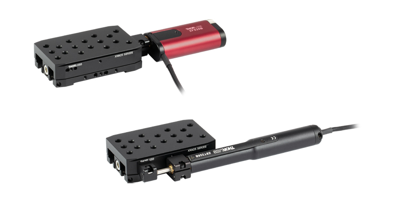
Compact Modular XRN25X 25 mm Stage |
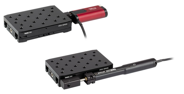
Modular XR25X 25 mm Stage |
LNR Series 25 mm Stage |
LNR Series 50 mm Stage |
|
| Click Photo to Enlarge |
 |
 |
 |
 |
 |
 |
|
| Travel | 13 mm | 1" (25.4 mm) | 25 mm | 25 mm | 50 mm | ||
| Speed | 5.0 mm/s | 7.0 mm/s (Max) | 2.0 mm/s (Max) | 2.0 mm/s (Max) | 50 mm/s (Max) | ||
| Possible Axis Configurations | Z | X, XY | X, XY, YZ, XZ, XYZ | X, XY, XYZ | X, XY, XYZ | ||
| Mounting Surface Size |
24.5 mm x 50.0 mm | 3" x 3" (76.2 mm x 76.2 mm) |
85.0 mm x 50.7 mm | 110.0 mm x 75.7 mm | 60.0 mm x 60.0 mm | 100.0 mm x 100.0 mm | |
| Additional Details | |||||||
| Stepper Motor Stages | ||||||
|---|---|---|---|---|---|---|
| Product Family | NRT Series 100 mm Stage |
NRT Series 150 mm Stage |
LTS Series 150 mm Stage |
LTS Series 300 mm Stage |
MLJ250 50 mm Vertical Stage |
|
| Click Photo to Enlarge |
 |
 |
 |
 |
 |
|
| Travel | 100 mm | 150 mm | 150 mm | 300 mm | 50 mm | |
| Max Speed | 30 mm/s | 50 mm/s | 3.0 mm/s | |||
| Possible Axis Configurations | X, XY, XYZ | X, XY, XYZ | Z | |||
| Mounting Surface Size | 84.0 mm x 84.0 mm | 100.0 mm x 90.0 mm | 148.0 mm x 131.0 mm | |||
| Additional Details | ||||||
DC Servo Motor Stages
Thorlabs offers linear translation stages with removable or integrated DC servo motors. These stages feature low profiles and many can be assembled in multi-axis configurations.
| DC Servo Motor Stages | ||||||
|---|---|---|---|---|---|---|
| Product Family | MT Series 12 mm Stages |
PT Series 25 mm Stages |
Compact Modular XNR25X 25 mm Stage |
Modular XR25X 25 mm Stage |
MTS Series 25 mm Stage |
MTS Series 50 mm Stage |
| Click Photo to Enlarge |
 |
 |
 |
 |
 |
 |
| Travel | 12 mm | 25 mm | 25 mm | 25 mm | 50 mm | |
| Max Speed | 2.6 mm/s | 2.6 mm/sa | 2.4 mm/s | |||
| Possible Axis Configurations |
X, XY, XYZ | X, XY, YZ, XZ, XYZ | X, XY, XYZ | |||
| Mounting Surface Size |
61.0 mm x 61.0 mm | 101.6 mm x 76.2 mm | 85.0 mm x 50.7 mm | 110.0 mm x 75.7 mm | 43.0 mm x 43.0 mm | |
| Additional Details | ||||||
| DC Servo Motor Stages | ||||
|---|---|---|---|---|
| Product Family | M30 Series 30 mm Stage |
M30 Series 30 mm Monolithic XY Stage |
M150 Series 150 mm XY Stage |
KVS30 30 mm Vertical Stage |
| Click Photo to Enlarge |
 |
 |
 |
 |
| Travel | 30 mm | 150 mm | 30 mm | |
| Max Speed | 2.4 mm/s | X-Axis: 170 mm/s Y-Axis: 230 mm/s |
8.0 mm/s | |
| Possible Axis Configurations | X, Z | XY, XZ | XY | Z |
| Mounting Surface Size | 115.0 mm x 115.0 mm | 272.4 mm x 272.4 mm | 116.2 mm x 116.2 mm | |
| Additional Details | ||||
Direct Drive Stages
These low-profile stages feature integrated brushless DC servo motors for high speed translation with zero backlash. When no power is applied, the platforms of these stages have very little inertia and are virtually free running. Hence these stages may not be suitable for applications where the stage's platform needs to remain in a set position when the power is off. We do not recommend mounting these stages vertically.
| Direct Drive Stages | |||||
|---|---|---|---|---|---|
| Product Family | DDS Series 50 mm Stage |
DDS Series 100 mm Stage |
DDS Series 220 mm Stage |
DDS Series 300 mm Stage |
DDS Series 600 mm Stage |
| Click Photo to Enlarge |
 |
 |
 |
 |
 |
| Travel | 50 mm | 100 mm | 220 mm | 300 mm | 600 mm |
| Max Speed | 500 mm/s | 300 mm/s | 400 mm/s | 400 mm/s | |
| Possible Axis Configurations | X, XY | X, XY | X | X | |
| Mounting Surface Size | 60 mm x 52 mm | 88 mm x 88 mm | 120 mm x 120 mm | ||
| Additional Details | |||||
100 mm Linear Translation Stage, Stepper Motor


Thorlabs' NRT100(/M) stage provides 100 mm of travel with an integrated stepper motor. Optomechanics can be directly mounted to the moving platform using eight 1/4"-20 (M6) tapped holes, which are spaced 1.0" (25.0 mm) apart.
Part Number | Description | Price | Availability |
|---|---|---|---|
NRT100/M | 100 mm Motorized Linear Translation Stage, Stepper Motor, M6 Taps | $2,442.36 | Today |
NRT100 | 100 mm Motorized Linear Translation Stage, Stepper Motor, 1/4"-20 Taps | $2,442.36 | Today |
Right-Angle Bracket for NRT Translation Stages
Click to Enlarge
XZ Assembly Constructed Using the NRT150P1 Right-Angle Bracket and Two NRT100 Translation Stages
Click to Enlarge
NRT100 Stage Mounted Vertically on an NRT150P1 Bracket Attached Directly to an Optical Table
- For Constructing XZ and XYZ Stage Assemblies
- Attaches Directly to an Optical Table for Applications Requiring One Axis of Vertical Translation
The NRT150P1(/M) is an anodized aluminum right-angle bracket that orients an NRT100(/M) or NRT150(/M) translation stage in the vertical axis. This allows for the construction of XZ and XYZ translation stage arrangements (XZ option shown to the far right). Alternatively, the NRT150P1 can be directly attached to an optical table for applications that require one axis of vertical translation (shown to the right).
The base of the NRT150P1(/M) contains six counterbored holes for 1/4"-20 (M6) cap screws, while its side has two 1/4"-20 (M6) tapped holes. The two side taps are designed to accept the vertically mounted stage.
Part Number | Description | Price | Availability |
|---|---|---|---|
NRT150P1/M | Right-Angle Bracket for NRT Translation Stages, M6 Taps | $177.00 | Today |
NRT150P1 | Right-Angle Bracket for NRT Translation Stages, 1/4"-20 Taps | $177.00 | Today |
Replacement Cables

- Replacement Motor Drive Cables
- Available Lengths: 1 m (3.3') and 3 m (9.9')
One PAA613 Motor Drive Cable is included with each of our NRT Series Translation Stages. Replacement cables are available here in case of loss or damage to the included cable.
These cables are also compatible with our stepper motor actuators. The male end connects to the controller and the female end connects to the motor.
Part Number | Description | Price | Availability |
|---|---|---|---|
PAA612 | Stepper Motor Cable, DA15 Male to DE15 Female, 1 m | $69.21 | Today |
PAA613 | Stepper Motor Cable, DA15 Male to DE15 Female, 3 m | $82.86 | 2 Weeks |