

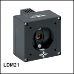
Miniature Temperature-Controlled Mount for TO-Can Laser Diodes

- Ø5.6 mm and Ø9.0 mm Laser Diode Mount with TEC
- Compact Housing Compatible with SM1 and 30 mm Cage System Products
- Compatible Pin Configurations: Style A, B, C, D, E, and H
LDM21
Front
Back
Application Idea
LDM21 Mount, SM1A6T and
S05TM08 Adapters, and Aspheric Lens
OVERVIEW
| Item # | LDM21(/M) |
|---|---|
| Laser Diode Package | 5.6 mm and 9 mm |
| Supported Pin Configurations | A, B, C, D, E, and H |
| Maximum Laser Current | 500 mA |
| Maximum Laser Input Powera | 600 mW |
| Laser Interface | DB9 Female |
| Polarity of Laser Diode | Selectable |
| Polarity of Monitor Diode | Selectable |
| Maximum TEC Current | 2.5 A |
| Maximum TEC Voltage | 1.8 V |
| TEC Heating / Cooling Capacity | 2 W |
| TEC Interface | DB9 Male |
| Temperature Sensor | 10 kΩ NTC Thermistor |
| Temperature Range (@ 25 °C) | 20 - 30 °C |
| Dimensions (W x H x D) | 1.75" x 1.75" x 1.66" (44.5 mm x 44.5 mm x 42.1 mm) |
Features
- Compact Mount for Ø5.6 mm and Ø9 mm Laser Diodes
- Pin Code Compatibility: A, B, C, D, E, and H
- SM1 Thread and 30 mm Cage System Compatible
The LDM21(/M) Miniature TE-Cooled Laser Diode Mount is capable of accepting both Ø5.6 mm and Ø9 mm laser diode packages. With an integrated thermal electric cooler element and a 10 kΩ thermistor, this mount keeps laser wavelengths stabilized by precisely holding the case temperature to within 0.2 °C. For more details on the operation and limitations of the temperature control, please see the TEC Operation tab. The small size of the LDM21(/M) makes this mount ideal for optical setups where space is limited.
This mount is compatible with our extensive line of Laser Diode and TEC Controllers and can operate laser diodes with A, B, C, D, E, and H pin configurations. Please see the Pin Configurations tab for more info. The front side of the mount has a standard SM1 (1.035"-40) thread, making it compatible with our Ø1" lens tubes and allowing for the addition of collimating or focusing optics. The back side of the mount accepts DB9 inputs from a laser current source and TEC controller. The housing has four 8-32 (M4 x 0.7) taps to attach the mount to a Ø1/2" post. An AS4M8E adapter with internal M4 threads is included to mount the LDM21 to metric posts.
Mounting collimating and other optics is easy using standard Thorlabs optomech parts. Step by step procedures for mounting optics and controlling the laser diode are found in the manual and the Controllers and LD Collimation tabs. Contact Tech Support for more information.
Pin Codes
Figure 1.1 The LDM21(/M) Mount is only compatible with A, B, C, D, E, and H pin code styles. These drawings do not represent exact wiring diagrams.
PIN CONFIGURATIONS
Figure 2.1 Supported and Unsupported Pin Configurations
Laser Diode Pin Configurations
Thorlabs offers several different laser diodes in the UV, visible, and NIR. Many laser diode packages also include a built-in monitor photodiode, and the electrical connections for the diodes vary based on the internal circuitry of the package. Thorlabs labels these different configurations, shown in Figure 2.1, as styles A through H. Thorlabs notes the pin configuration styles of the diodes we offer both in the specifications provided on our website and on the specification sheets included with the diodes. To determine the style of any laser diode package, compare its pin diagram supplied with the styles shown in Figure 2.1. Use the style type, pin configuration, and the following information to properly power the laser diode.
The laser diode orientation is engraved on the front of the LDM21 mount and also shown in Figure 2.2.
LDM21 Mount Compatibility
The LDM21 Laser Diode Mount is compatible with all three-pin Ø5.6 mm and Ø9 mm laser diode packages that have an A, B, or C pin configuration style. These configurations include both a laser diode and a monitor photodiode, and the packages feature a common ground pin and independent control of the Laser Diode (LD) and Photodiode (PD) voltages.
 Figure 2.2 The LDM21 has a standard 4-pin mounting configuration.
This mount is also compatible with style E and H laser diodes, which do not possess a monitor photodiode. These are three-pin packages that include a laser diode pin and a ground pin, as shown in Figure 2.1.
Lastly, the LDM21 mount is also compatible with all of our currently available four-pin laser diodes possessing a style D configuration (see Figure 2.1). As with style A, B, and C laser diodes, style D laser diodes feature a laser diode and monitoring photodiode; however, the photodiode floats with respect to the case in style D packages.
The LDM21 mount is NOT compatible with style F or G configurations. These pin configurations have pin layouts that prohibit their use in this mount. Please see our high-power laser diode mounts for compatibility with these pin configurations.
Full details of the assembly and operation of the LDM21 Mount can be found in the operating manual.
PIN DIAGRAMS
| Label | Descriptiona |
|---|---|
| GND | Ground |
| LD | Laser Diode Cathode or Anode |
| PD | Photodiode Cathode or Anode |
LD Driver
9-Pin D-Type Female
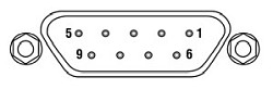
| Pin | Signal | Description |
|---|---|---|
| 1 | Interlock (LDC Specific) | This pin is the input to the Interlock Circuits. When using Thorlabs LDCs no external circuitry is required. |
| 2 | Photodiode Cathode | This pin is connected to the 9 o'clock pin on the laser socket when the PD Polarity Switch is set to anode ground (AG). It is attached to ground and the 12 o'clock and 6 o'clock pins on the laser socket when the PD Polarity Switch is set to cathode ground (CG). |
| 3 | Laser Ground (Case) | This pin is connected to the 12 o'clock and 6 o'clock pins on the laser socket and corresponds to the settings of the LD and PD polarity switches. i.e. If the LD and PD switches are set to AG then this pin grounds the Anodes of the laser and photo diodes. |
| 4 | Photodiode Anode | This pin is connected to the 9 o'clock pin on the laser socket when the PD Polarity Switch is set to CG. It is attached to ground and the 12 o'clock and 6 o'clock pins on the laser socket when the PD Polarity Switch is set to AG. |
| 5 | Interlock Return | This pin is the return side of the Interlock circuitry. Pin 1 and 5 are shorted internally in the LDM21. |
| 6 | N.C. | Not Used. |
| 7 | Laser Diode Cathode | This pin is connected to the 3 o'clock pin on the laser socket when the LD Polarity Switch is set to AG. Otherwise it is floating. |
| 8 | Laser Diode Anode | This pin is connected to the 3 o'clock pin on the laser socket when the LD Polarity Switch is set to CG. Otherwise it is floating. |
| 9 | N.C. | Not Used. |
TEC Controller
9-Pin D-Type Male

| Pin | Signal | Description |
|---|---|---|
| 1 | N.C. | Not Used |
| 2 | +Thermistor | The 10 kΩ at 25 °C NTC thermistor (provided for temperature feedback). |
| 3 | -Thermistor | The thermistor return pin. |
| 4 | +TEC | This pin is connected to the positive terminal of the TEC element. |
| 5 | -TEC | This pin is connected to the negative terminal of the TEC element. |
| 6 | N.C. | Not Used. |
| 7 | AD592(-) | The negative terminal of the AD592 temperature transducer. When using Thorlabs TEDs no external circuitry is required. To use this device with third party controllers it must be properly biased. Refer to Analog Devices AD592 Data for application information. |
| 8 | N.C. | Not Used. |
| 9 | AD592(+) | The positive terminal of the AD592 |
CONTROLLERS
Laser Diode Current Controllers
The laser diode current controller should be chosen to be compatible with the particular laser diode and application. Thorlabs offers a wide variety of laser diode controllers ranging from low power (low current and low voltage) to high power (high current and/or voltage) versions. Thorlabs also offers several dual laser diode current/temperature controllers. See the TEC Controllers section that follows for discussion of the temperature controllers.
Thorlabs' LDC2xxC series of controllers are suitable for use with a large majority of popular laser diodes. Thorlabs' LDC200CV is specifically designed to handle and safely operate Vertical Cavity Surface Emitting Lasers (VCSELs), while the LDC201CU provides users with an ultra-low noise current (<0.2 μA RMS) for stable operation of low power laser diodes. If your application requires the higher voltages typically necessary for driving blue and other short laser diodes, consider our LDC202C, LDC205C, or LDC210C controller. For driving higher power laser diodes, the LDC220C and LDC240C offer drive currents of 2 A and 4 A, respectively. Higher current (5 and 20 A), T-Cube-compatible, and rack mount controllers are also available. All of these controllers operate in a similar manor. Only the LDC2xxC series controllers will be discussed in more detail.
Click to Enlarge
Figure 4.1 TEC Operation Limits
TEC Controllers
Thorlabs also offers a wide variety of TEC controllers as stand-alone units and dual laser diode/ temperature controllers. The TED200C benchtop temperature controller is ideally suited to regulate the temperature of a laser diode mounted in our LDM21(/M) Laser Diode Mount. This unit features a wide operating temperature range, 12 W of cooling, and high temperature stability. For more cooling power and even higher temperature stability, the TED4015 225 W temperature controller can be used.
The TEC elements in these mounts can be connected to a temperature controller via the DB9 female connection on the side of the unit. Adapter cables are available for temperature controllers with other connector types. For third-party controllers, please refer to the operating manual for pin layouts and descriptions. Follow the instructions for the TEC controller, paying careful attention not to overdrive the TEC elements in the mount.
TEC Operation Limits
The LDM21(/M) mount is intended to be operated at a fixed temperature setpoint of 25 °C but can be operated as low as 20 °C as long as the input power to the laser diode (LD current x LD voltage) does not exceed the values specified in the Safe Operating Area curve, as shown in Figure 4.1, as a function of ambient temperature. It is not recommended that the LDM21(/M) be driven with more than 600 mW of input power, set to a temperature below 20 °C, or operated in an ambient temperature above 35 °C. Operating the LDM21(/M) outside of the safe operating area (the area under the curve in Figure 4.1) will result in damage to the laser diode.
LD COLLIMATION
Choosing Collimation and Ellipticity Correction Optics for Your Laser Diode
Since the output of a laser diode is highly divergent, collimating optics are often necessary. Due to their excellent ability to correct spherical aberration, aspheric lenses are the most commonly used optics when the desired collimated beam waist is between one and five millimeters. Choosing an appropriate aspheric lens for collimating a laser diode is essential, as the resulting beam size and transmission range are dependent on the lens used. To calculate the beam size of a collimated laser diode, we first need to know its divergences.
The beam divergences of an edge-emitting laser diode will be different in the parallel and perpendicular directions, leading to an elliptical beam. This can be compensated for by inserting anamorphic prism pairs or cylindrical lenses into the collimated beam. The divergences are typically specified as "Beam Divergence (FWHM) - Parallel" and "Beam Divergence (FWHM) - Perpendicular" for the two axes of the chip. There are variations from lot to lot of laser diodes, but using the typical divergence values should be adequate for most applications.
The simple example below will illustrate the key specifications to consider when choosing the correct optics for a given application.
Example: 785 nm, 25 mW Laser Diode, L785P25, Ø3 mm Desired Collimated
Step 1: Collimating Emission
The specifications for the L785P25 laser diode indicate that the typical perpendicular and parallel beam divergences are 30o and 8o, respectively. The major (perpendicular) beam divergence is shown in Figure 1. The minor (parallel) beam divergence is shown in Figure 2. Because of this asymmetry in the two axes, an elliptical beam will form as the light diverges. To collect as much light as possible during the collimation process, consider the larger of these two divergence angles in any calculations (i.e., in this case use 30o).
Note: Parallel and perpendicular notation are specified relative to the junction plane of the laser diode.
Figure 1. Perpendicular beam divergence from L785P25 style B laser diode
Figure 2. Parallel beam divergence from L785P25 style B laser diode
In the above schematics, LD denotes the laser diode,  and
and  are the beam diameters in the parallel and perpendicular orientations, respectively, and
  and
and  are the divergence angles in the parallel and perpendicular orientations, respectively. Please note that the notch in Figures 1 and 2 can be used to determine the orientation of the laser diode within the package. Laser diodes are typically oriented parallel to the notch; however there are many exceptions, especially for different laser diode packages. Care should be taken to note the orientation of the laser diode emission.
To calculate the focal length needed to achieve a Ø3 mm collimated beam diameter, we can use:
where  is the focal length that produces the desired perpendicular beam diameter, . The focal length of the lens needed to collimate a 30o diverging beam into a Ø3 mm collimated beam is = 5.6 mm.
This equation yields the focal length to achieve our desired major (perpendicular) axis diameter. Use this to then select an aspheric lens with a focal length that most closely matches the focal length given by the equation. Please note that the diameter of the lens must be larger than your desired major axis beam diameter.
Thorlabs offers a large selection of aspheric lenses. For this application, the ideal lens is an -B AR-coated molded glass aspheric lens with focal length near 5.6 mm. The C171TMD-B (mounted) or 354171-B (unmounted) aspheric lenses have a focal length of 6.20 mm. Next, check to see if the numerical aperture (NA) of the diode is smaller than the NA of the lenses so that the light emitted from the laser diode is not clipped by the lens:
0.30 = NALens > NADiode ~ sin(15) = 0.26
Figure 3. Anamorphic Prism Pair and optic trace for an ellipse to round beam.
Solving the first equation again with your actual focal length and major axis divergence angle yields the actual major axis beam diameter, = 3.3 mm.
Step 2: Correcting Ellipticity
Emission from an edge emitting laser diode is elliptical (asymmetric with respect to two different axes), as shown in Figures 1 and 2. To correct for this and produce a circular beam, the minor axis diameter, , can be magnified using anamorphic prism pairs or cylindrical lenses after collimation. Note: only cylindrical lens pairs can correct for any astigmatism present in the diode output. Figure 3 shows an anamorphic prism pair magnifying an elliptical beam minor axis to produce the desired symmetric beam.
To determine what magnification of the minor axis is needed to produce a round beam, solve Eq. 1 using the focal length from the aspheric lens,![]() = 6.20 mm, = 8o, instead of the major axis divergence. This results in a minor axis diameter, = 0.9 mm. Comparing and , we see that a 3.5X magnification is necessary in the minor beam axis. This 3.5X magnification can be achieived using the PS881-B Mounted Anamorphic Prism Pair.
= 6.20 mm, = 8o, instead of the major axis divergence. This results in a minor axis diameter, = 0.9 mm. Comparing and , we see that a 3.5X magnification is necessary in the minor beam axis. This 3.5X magnification can be achieived using the PS881-B Mounted Anamorphic Prism Pair.
Lens Tube Mounting
For mounted aspheric lenses, our SM05Txx or S1TMxx adapters can be used. Take care to ensure that the lens does not contact the laser diode. The SM05Txx adapters will require the use of an SM1A6T SM1-to-SM05 adapter.
Unmounted aspheres can be epoxied to an LMRAxx adapter, which can then be mounted in an SM1A6T SM1-to-SM05 adapter. The SM1 threading of the adapter can then be used to attach the lens/mount/adapter to the laser diode mount's front plate. The SM1A6T adapter has a mounting range of 10 mm, covering almost the entire focal length range of our aspheric lenses.
In the above example, the C171TMD-B mounted lens features M8 x 0.5 threading, thus requiring the S05TM08-threaded adapter. The S05TM08 M8-to-SM05 adapter can be mounted in the laser diode mount using the SM1A6T SM- to-SM05 adapter. The correct distance between the laser diode and lens can be achieved by adjusting both the S05TM08 and the SM1A6T adapters.
If the 354171-B, unmounted ashperic lens is used, it must first be epoxied to the LMRA5 adapter. It can then be mounted in the SM1A6T SM1-to-SM05 adapter. Again, adjustment of the aspheric lens can be made at the LMRA5 and SM1A6T adapters.
Cage Assembly Mounting
Mounted and unmounted aspheric lenses with focal lengths greater than 8 mm can be cage mounted using our 30 mm cage system. Cage rods can be attached directly to the front plate of the laser diode mount. The CP33(/M) cage plate may be used to hold the S1TMxx adapter with mounted aspheric lens or the SM1A6T adapter with unmounted aspheric lens epoxied to an LMRAxx adapter.
For larger translational adjustments, the CT1A(/M) 1/2" Travel Translator can be used. The CT1A(/M) translator has a graduated micrometer which provides 1/2" (13 mm) of linear translation and has 0.001" (10 µm) graduations. The smallest incremental movement of the carriage is approximately 1 µm.
Anamorphic Prism Pair Mounting
The asymmetric output of the laser diode can be corrected using either anamorphic prisms or cylindrical lenses. As determined in the example above, a 3.5X mounted anamorphic prism pair (i.e., PS881-B) was needed to produce a round beam profile. Unmounted prisms may be used as well.
The PS881-B Mounted Anamorphic Prism Pair features SM05 threading on the output end or may be mounted inside an SM1 Lens tube. Since the input and output beams from the Anamorphic Prism Pair are offset from each other, prisms should be mounted on another cage or lens tube axis.
LD SETUP
Video Insight: Setting Up a TO Can Laser Diode
Installing a TO can laser diode in a mount and setting it up to run under temperature and current control presents many opportunities to make a mistake that could damage or destroy the laser. This step-by-step guide includes tips for keeping humans and laser diodes safe from harm.
If you would like more information about tips, tricks, and other methods we often use in the lab, we recommend our other Video Insights. In addition, our webinars provide practical and theoretical introductions to our different products.
LD MOUNT SELECTION GUIDE&NBSP;
| Laser Diode Mount Selection Guide | |||||||
|---|---|---|---|---|---|---|---|
| Item # | LDM38(/M) | LDM56(/M) | LDM56F(/M) | LDM90(/M) | LDM21 | LDM9T(/M) | |
| Click Photo to Enlarge |  |
 |
 |
 |
 |
 |
|
| Laser Diode | |||||||
| Supported Laser Diode Package(s) | Ø3.8 mm | Ø5.6 mm | Ø5.6 mm | Ø9 mm | Ø5.6 mm and Ø9 mm | Ø5.6 mm and Ø9 mm | |
| Supported Pin Configuration(s) | G | A, B, C, D, E, Ga, H (Switch Selectable) |
F and G (Switch Selectable) |
A, B, C, D, E, Ga, H (Switch Selectable) |
A, B, C, D, E, and H | A, B, C, D, E, G, and H (Some Modification Necessary for G Style)b |
|
| Maximum Laser Current (Tambient = 25 °C) |
1 A | 2 A | 500 mA | 200 mA | |||
| RF Modulation Frequency Rangec | 100 kHz to 500 MHz | 100 kHz to 600 MHz | N/A | 200 kHz to 1 GHz | |||
| Temperature Controller | |||||||
| TEC Heating/Cooling Capacity (Tambient = 25 °C) |
8 W | 8 W | 2 W | 0.5 W | |||
| Temperature Adjustment Range | - | 0 to 70 °C | 20 to 30 °C | ||||
| General Specifications | |||||||
| Laser Interface | DB9 Female | ||||||
| TEC Interface | DB9 Male | N/Ad | |||||
| Compatible Current and Temperature Controllers | LDC Series and T-Cube LD Controllerse, ITC Series Combined LD/TEC Controllersf, and Temperature Controllersf | LDC Series and T-Cube LD Series Controllerse |
|||||
| Mounting Features | Imperial Mounts | 1/4"-20 Tapped Hole (9 Places) | 8-32 Tapped Holeg (4 Places) |
8-32 Tapped Hole (3 Places) |
|||
| Metric Mounts | M6 x 1.0 Tapped Hole (9 Places) | N/A | M4 x 0.7 Tapped Hole (3 Places) |
||||
| Accommodations for Collimating Optics | SM1 (1.035"-40) Series Internal Thread; LDMXY Flexure Adapter (Sold Separately) |
SM1 (1.035"-40) Series Internal Thread | |||||
| Cage System Compatibility | 4-40 Tap (8 Places) for 30 mm and 60 mm Cage Systems |
4-40 Tap (4 Places) for 30 mm Cage System | |||||
| Dimensions | 4.00" x 4.00" x 2.07" (101.6 x 101.6 x 52.6 mm) |
1.75" x 1.75" x 1.66" (44.5 x 44.5 x 42.1 mm) |
3.09" x 2.89" x 1.79" (78.5 x 73.3 x 45.5 mm) |
||||
Miniature Temperature-Controlled Mounts
- Compact Mount for Ø5.6 mm and Ø9 mm Laser Diodes
- Supports A, B, C, D, E, and H Pin Configuration
The LDM21(/M) Miniature TE-Cooled Laser Diode Mount accepts both Ø5.6 mm and Ø9 mm laser diode packages with A, B, C, D, E, or H pin codes. SM1 (1.035"-40) threads provide compatibility with our Ø1" lens tubes, and 4-40 holes provide compatibility with Thorlabs' 30 mm cage system. For more information on the mount, including laser diode and controller compatability, see the tabs above.
Part Number | Description | Price | Availability |
|---|---|---|---|
LDM21/M | TE-Cooled Mount for Ø5.6 and Ø9.0 mm Laser Diodes with A/B/C/D/E/H Pin Codes, M4 x 0.7 Taps | $400.33 | Today |
LDM21 | TE-Cooled Mount for Ø5.6 and Ø9.0 mm Laser Diodes with A/B/C/D/E/H Pin Codes, 8-32 Taps | $400.33 | Today |
SM1-Threaded Adapter and Locking Ring
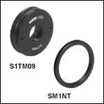
The S1TM09 Lens Cell Adapter adapts an internally SM1-threaded component to a component with external M9 x 0.5 threads. The adapter has two Ø0.05" (Ø1.2 mm) holes for use with a SPW909 and SPW801 spanner wrench.
The SM1NT Locking Ring has internal SM1 threads to secure the position of externally SM1-threaded components. The locking ring can be tightened by hand to secure the components.
Part Number | Description | Price | Availability |
|---|---|---|---|
S1TM09 | SM1 to M9 x 0.5 Lens Cell Adapter | $26.73 | Today |
SM1NT | SM1 (1.035"-40) Locking Ring, 1.25" Outer Diameter | $7.59 | Today |