Stepper Motor Control Module

- Two 50 W 2-Phase Bi-Polar Stepper Drive Outputs
- Motor Speeds up to 3000 RPM
- 409 600 Microsteps per Revolution of Motor
- Seamless Operation with Thorlabs and 3rd Party Motors/Stages
Full Suite of Software Support
Tools Included
MST602
OVERVIEW
| Rack System Modules |
|---|
| 2-Channel Piezo Controller Module |
| 2-Channel Stepper Motor Controller Module |
| 2-Channel NanoTrak® Auto-Alignment Module |
| 2-Channel Brushless DC Motor Controller Module |
| USB Motion Control 19" Rack Chassis |
| All Thorlabs' Rack System Modules require the use of the MMR601 or MMR602 Rack System Enclosure. Independent operation of the modules outside the enclosure is not possible. |
Features
- Two Stepper Motor Drive Channels
- High Resolution Microstepping Control (For Very Fine Positioning Applications)
- Stable and Predictable Low-Speed Operation (For Velocity Sensitive Applications)
- Supports 2-Phase Bipolar Steppers up to 48 V / 50 W Peak
- Differential Encoder Feedback (QEP Inputs) for Closed-Loop Positioning
- USB Plug and Play for Multi-Axis Expansion
- Motor Control I/O Port (Jogging, Interlocks)
- Kinesis® Software Control Suite Included
- Intuitive Software Graphical Control Panels
- Fully Software Integrated with Other Thorlabs Motion Controllers (Integrated Systems Development)
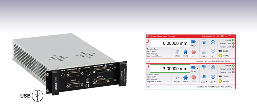
The MST602 module is a dual-channel, high-resolution, rack-mounted stepper motor driver designed for use with the MMR601 or MMR602 Motion Control 19" Modular Rack System. It has been designed to drive 2-phase bi-polar stepper motors up to 50 W, with or without encoder feedback, and is compatible with the full range of stepper-motor-equipped nanopositioning actuators and stages offered by Thorlabs. Alternatively, it is also compatible with any generic two-phase bi-polar motor of varying powers and varying cardinal step sizes.
This stepper motor controller has been designed specifically to operate with the highly flexible MMR601 or MMR602 Motion Control 19" Modular Rack System. Up to 6 MST602 stepper modules can be fitted to a given rack system, providing a scalable motion control solution for multi-axis motion control applications. For stand-alone controller options, please see the table below.
When used with a MMR601 or MMR602 Rack enclosure, this unit can be used with a PC via USB connection. Multiple modules can be connected to a single PC via standard USB hub technology for multi-axis motion control applications. Coupling this with the user-friendly Kinesis software allows the user to get up and running very quickly. Advanced custom motion control applications and sequences are also possible using the extensive Kinesis programming environment, which is described in more detail in the Kinesis Software tab.
An optional 2-axis joystick console (item # MJC001) is also available for tactile, manual positioning of a stage. See the manual, found by clicking on the red Docs icon (![]() ), for more information on using the joystick console.
), for more information on using the joystick console.
Cabling
Cables for connecting actuators or stages to the controller are shipped with the actuators or stages, not the controller. If you need help identifying the appropriate replacement cable, please contact Tech Support.
| Other Stepper Motor Controllers | ||
|---|---|---|
| K-Cube Single-Channel Controller | 1-, 2-, and 3-Channel Benchtop Controller | Modular 2-Channel Rack System Module |
SPECS
Module Specifications
| Motor Drive Connector (15-Pin D-Type Female) Per Channel | |
|---|---|
| 2 Phase Bipolar Motor Drive Output | Forward, Reverse Limit Switch Inputs |
| Differential Quadrature Encoder (QEP) Input | Encoder 5 V (with Ground) |
| Motor Control Connector (15-Pin D-Type Female) | |
| Jog Forward/Back Input | TTL Level |
| Enable/Disable Interlock (Per Channel) | Connect to Return to Operate Motor |
| User 5 V (with Ground) 100 mA Max | |
| User I/O Connector (26-Pin D-Type Female) | |
| 4 Logic Inputs | TTL Level |
| 4 Logic Outputs | Open Collector |
| Trigger Input | TTL Level |
| Trigger Output | Open Collector |
| 2 Analogue Inputs | Single Ended 0 - 10 V (12-bit) |
| Motor Resolution | |
| 2048 Microsteps per Full Step | |
| For 200 Step Motor - 409 600 Microsteps/Rev | |
| For 24 Step Motor - 49 152 Microsteps/Rev | |
| Motor Drive Voltage | Up to 48 V |
| Motor Drive Power | Up to 50 Wpeak/25 Wave |
| Motor Speeds | Up to 3000 RPM (200 Full Step Motor) |
| Encoder Feedback Bandwidth | 500 kHz |
| General | |
| Housing | Single Rack System Bay |
| Dimensions (W x D x H) | 190 x 270 x 50 mm (7.5" x 10.6" x 2") |
| Weight | 1.5 kg (3.3 lbs) |
Compatible Motor Specifications
| Specification | Value |
|---|---|
| Peak Powers | 5 to 50 W |
| Average Power | 25 W Maximum |
| Step Angle Range | 20° to 1.8° |
| Coil Resistance (Nominal) | 4 to 15 Ω |
| Coil Inductance (Nominal) | 4 to 15 mH |
| Rated Phase Currents (Nominal) | 100 mA to 1 A |
PIN DIAGRAMS
Motor I/O Controller
D-type Female

| Pin | Description | Return | Pin | Description | Return | Pin | Description | Return |
|---|---|---|---|---|---|---|---|---|
| 1 | User 5 V I/O | 9 | 6 | Channel 2 Emergency Stop Daisy Chain Link Returnb | 14 | 11 | Channel 2 Jog Backwardsa | 9 |
| 2 | Channel 1 Jog Forwardsa | 9 | 7 | Channel 2 Enable Returnb | 15 | 12 | Channel 1 Emergency Stop Daisy Chain Linkb | 4 |
| 3 | Channel 2 Jog Forwardsa | 9 | 8 | Not Used | - | 13 | Channel 1 Enableb | 5 |
| 4 | Channel 1 Emergency Stop Daisy Chain Link Returnb | 12 | 9 | User 0V | - | 14 | Channel 2 Emergency Stop Daisy Chain Linkb | 6 |
| 5 | Channel 1 Enable Returnb | 13 | 10 | Channel 1 Jog Backwardsa | 9 | 15 | Channel 2 Enableb | 7 |
User I/O Controller
D-type Female

| Pin | Description | Return | Pin | Description | Return | Pin | Description | Return |
|---|---|---|---|---|---|---|---|---|
| 1 | Digital I/P 1 | 19 | 10 | Digital O/P 1 | 19 | 19 | Digital Ground 1 (0 V)a | - |
| 2 | Digital I/P 2 | 19 | 11 | Digital O/P 2 | 19 | 20 | Ext Trigger I/P | 22 |
| 3 | Digital I/P 3 | 19 | 12 | Digital O/P 3 | 19 | 21 | Ext Trigger O/P | 22 |
| 4 | Digital I/P 4 | 19 | 13 | Digital O/P 4 | 19 | 22 | Digital Ground 2 (0 V)a | - |
| 5 | Channel 1 RS232 TX | - | 14 | Channel 2 RS232 TX | - | 23 | 5 V User O/P (50 mA Max.) | - |
| 6 | Channel 1 RS232 RX | - | 15 | Channel 2 RS232 RX | - | 24 | Reserved for Future Use | - |
| 7 | Not Used | - | 16 | Reserved for Future Use | - | 25 | Reserved for Future Use | - |
| 8 | Channel 2 Analog I/P (+)b | 17 | 17 | 0 V (Analog Rtn)b | 8 | 26 | Analog Ground (0 V)a,c |
- |
| 9 | Channel 1 Analog I/P (+)b | 18 | 18 | 0 V (Analog Rtn)b | 9 |
Drive Channel Connector
D-type Female

| Pin | Description | Pin | Description | Pin | Description |
|---|---|---|---|---|---|
| 1 | Encoder A +ve | 6 | Not Used | 11 | 0 V User |
| 2 | Encoder A -ve | 7 | Phase B - | 12 | Reserved for Future Use |
| 3 | Encoder B +ve | 8 | Phase A - | 13 | Reserved for Future Use |
| 4 | Encoder B -ve | 9 | CW Limit Switch | 14 | Phase B + |
| 5 | 5 V User | 10 | CCW Limit Switch | 15 | Phase A + |
Handset
Mini DIN Female

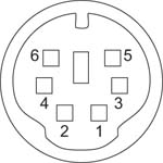
| Pin | Description | Pin | Description |
|---|---|---|---|
| 1 | RX (Controller Input)/RS232 | 4 | Supply Voltage for Handset 5V |
| 2 | Ground | 5 | TX (Controller Output) |
| 3 | Ground | 6 | Ground |
KINESIS SOFTWARE
Software
Kinesis Version 1.14.50
The Kinesis Software Package, which includes a GUI for control of Thorlabs' Kinesis system controllers.
Also Available:
- Communications Protocol

Kinesis GUI Screen
Thorlabs offers the Kinesis® software package to drive our wide range of motion controllers. The software can be used to control devices in the Kinesis family, which covers a wide variety of motion controllers ranging from small, low-powered, single-channel drivers (such as the K-Cubes™) to high-power, multi-channel benchtop units and modular 19" rack nanopositioning systems (the MMR60x Rack System).
The Kinesis Software features .NET controls which can be used by 3rd party developers working in the latest C#, Visual Basic, LabVIEW™, or any .NET compatible languages to create custom applications. Low-level DLL libraries are included for applications not expected to use the .NET framework and APIs are included with each install. A Central Sequence Manager supports integration and synchronization of all Thorlabs motion control hardware.
By providing this common software platform, Thorlabs has ensured that users can mix and match any of our motion control devices in a single application, while only having to learn a single set of software tools. In this way, it is perfectly feasible to combine any of the controllers from single-axis to multi-axis systems and control all from a single, PC-based unified software interface.
The software package allows two methods of usage: graphical user interface (GUI) utilities for direct interaction with and control of the controllers 'out of the box', and a set of programming interfaces that allow custom-integrated positioning and alignment solutions to be easily programmed in the development language of choice.
2-Channel Stepper Motor Control Module

Part Number | Description | Price | Availability |
|---|---|---|---|
MST602 | Modular 2-Channel Stepper Motor Controller | $1,553.63 | Today |
