
Photodiode Power Sensors (C-Series)

- Power Ranges Covering 100 pW to 20 W
- Wavelength Ranges Covering 200 nm to 5.5 µm
- C-Series Connector for Quick Exchange
S120C
Sensor with IR
Target
S145C
Integrating Sphere Sensor
Posts and Post Holders Not Included
S140C
Integrating Sphere Sensor
S130C
Slim Sensor
S154C
Fiber Sensor
S170C
Microscope Slide
Power Sensor Head
Integrating Sphere Sensors Shown with FC/PC Adapters (Included on Sensors with Apertures ≤Ø12 mm)
Articulating Arm Not Included
S116C
Compact Slim Sensor
OVERVIEW
| Power Meter Selection Guide |
|---|
| Sensors |
| Photodiode Power Sensors |
| Thermal Power Sensors |
| Thermal Position & Power Sensors |
| Pyroelectric Energy Sensors |
| Power Meter Consoles and Interfaces |
| Digital Handheld Consoles |
| Analog Handheld Console |
| Touchscreen Handheld Console |
| Dual-Channel Benchtop Console |
| USB Interfaces with External Readout |
| Complete Power Meters |
| Power Meter Bundles |
| Wireless Power Meters with Sensors |
| Compact USB Power Meters |
| Field Power Meters for Terminated Fibers |
Features
- Fast Response Time and High Resolution
- C-Series Connector Design for Quick Sensor Connection
- Over-Temperature Alert Sensor (Except S130 Series and S170C and NS170C Microscope Slide Sensors)
- Individually Calibrated with NIST- or PTB-Traceable Certificate of Calibration Plus Embedded Calibration Curve and Sensor Settings
Thorlabs' C-Series Photodiode Power Meter Sensors cover a wide power and wavelength range. These sensors are offered in standard, slim, microscope slide, integrating sphere, and compact fiber versions to meet your specific application requirements. They are the best sensor choice when a fast response time or high resolution is required and there is not a need for a flat spectral response.
These photodiode power meter sensors feature enhanced shielding to avoid electromagnetic interference as well as an over-temperature alert sensor to warn against damage and measurement errors due to overheating of the sensor (except the S130VC, S130C, and S132C Slim Sensors and the S170C and NS170C Microscope Slide Sensors). For all sensors (except the S130VC, S130C, and S132C Slim Sensors and the S170C and NS170C Microscope Slide Sensors), a set of fiber adapters is available to connect them to standard optical fiber patch cables (see below). Other fiber adapter types are available upon request.
The sensors below (except the S150C series) have universal 8-32 and M4 taps for mounting to Ø1/2" Posts. Posts and post holders are not included and sold separately. Please see the Mounting Options tab for more information.
Compatibility
The Photodiode Sensors presented here are compatible with C-Series power meter consoles including the PM100A, PM100D2, PM100D3, PM400, and PM5020, as well as many of our C-series power and energy meter interfaces. The S150C Series Fiber Sensors are integrated into the connector itself and directly plugged into the console.
Calibration
Each sensor head is individually calibrated and is shipped with NIST- or PTB-traceable calibration data. The included data will match the calibration certification of the photodiode used to test the individual sensor. The calibration and identification data are stored in the connector of the sensor and are downloaded automatically to the connected power meter console.
Sensor Upgrade Service
All C-Series Sensors are incompatible with old power meter consoles with non-C-Series connectors. We offer a sensor upgrade service if you want to use your existing sensors with a new power meter console with C-Series connector. Note: upgraded sensors will be incompatible with old power meter consoles with non-C-Series connectors. Please contact our Tech Support team for details.
Recalibration Services
Recalibration services are available for all our photodiode power sensors. We recommend your Thorlabs sensor and console be recalibrated as a pair annually; however, each may be recalibrated individually. All of the sensors on this page come with a manufacturer calibration by default, but we also offer an ISO 17025 accredited calibration for some items. For more information on calibration options, please see the Recalibration tab or the calibration sections at the bottom of this page.
| Photodiode Sensor Selection Guide | ||||||
|---|---|---|---|---|---|---|
| Housing Type | Standard | Slim | Compact Slim | Microscope Slide | Integrating Sphere | Fiber-Coupled |
| Power Range | 50 nW - 500 mW | 500 pW - 500 mW | 20 nW - 50 mW | 1 nW - 350 mW | 1 µW - 20 W | 100 pW - 20 mW |
| Wavelength Range | 200 nm - 1800 nm | 200 nm - 1800 nm | 400 nm - 1100 nm | 350 nm - 1300 nm | 350 nm - 5500 nm | 350 nm - 1700 nm |
| Typical Application | General Measurement | Tight Places | Microscope Alignment and Calibration |
Divergent Beams | Fiber | |
| Fiber Adapters Available | Yes | Yes | Yes | No | Yesa | Yes |
SPECS
These specifications were obtained at an ambient room temperature of 23 °C ± 0.5 °C and a humidity of 45% ± 15%.
For details on sensor-related terminology, see our list of definitions.
Standard Photodiode Sensors: S120C Series
| Item # | S120VC | S120C | S121C | S122Ca |
|---|---|---|---|---|
| Technical Specs | ||||
| Detector Type | Silicon Photodiode (UV Extended) | Silicon Photodiode | Silicon Photodiode | Germanium Photodide |
| Wavelength Range | 200 nm - 1100 nm | 400 nm - 1100 nm | 400 nm - 1100 nm | 700 nm - 1800 nm |
| Optical Power Range | 50 nW - 50 mW (200 nm - 450 nm) 50 nW - 20 mW (450 nm - 1100 nm) |
50 nW - 50 mW | 500 nW - 500 mW | 50 nW - 40 mW |
| Max Average Power Densityb | 20 W/cm² | 10 W/cm² | ||
| Max Pulse Energy | 20 µJ | |||
| Linearity | ±0.5% | |||
| Resolutionc | 1 nW | 1 nW | 10 nW | 2 nW |
| Measurement Uncertaintyd | ±3% (440 nm - 980 nm) ±5% (280 nm - 439 nm) ±7% (200 nm - 279 nm, 981 nm - 1100 nm) |
±3% (440 nm - 980 nm) ±5% (400 nm - 439 nm) ±7% (981 nm - 1100 nm) |
±3% (440 nm - 980 nm) ±5% (400 nm - 439 nm) ±7% (981 nm - 1100 nm) |
±5% |
| Responsivitye (Click for Details) | Raw Data |
Raw Data |
Raw Data |
Raw Data |
Compact Slim Photodiode Sensor
| Item # | S116C | ||
|---|---|---|---|
| Technical Specs | |||
| Detector Type | Silicon Photodiode | ||
| Wavelength Range | 400 nm - 1100 nm | ||
| Optical Power Working Range |
20 nW - 50 mW | ||
| Max Average Power Densitya |
20 W/cm² | ||
| Max Pulse Energy | 20 µJ | ||
| Linearity | ±0.5% | ||
| Resolutionb | 1 nW | ||
| Measurement Uncertaintyc |
±3% (440 nm - 980 nm) ±5% (400 nm - 439 nm, ±7% (981 nm - 1100 nm) |
||
| Responsivityd (Click for Details) |
Raw Data |
||
Slim Profile Photodiode Sensors: S130C Series
| Item # | S130VC | S130C | S132Ca | |
|---|---|---|---|---|
| Technical Specs | ||||
| Detector Type | Silicon Photodiode(UV Extended) | Silicon Photodiode | Germanium Photodiode | |
| Wavelength Range | 200 nm - 450 nm | 450 nm - 1100 nm | 400 nm - 1100 nm | 700 nm - 1800 nmb |
| Optical Power Range (with Filter) | 500 pW - 0.5 mW (Up to 50 mW)c |
500 pW - 0. mW (Up to 20 mW)c |
500 pW - 5 mW (Up to 500 mW) |
5 nW - 5 mW (Up to 500 mW) |
| Max Average Power Densityd |
20 W/cm² | 10 W/cm² | ||
| Max Pulse Energy | 20 µJ | |||
| Linearity | ±0.5% | |||
| Resolution | 100 pWe | 100 pWe | 1 nWf | |
| Measurement Uncertaintyg |
±3% (440 nm - 980 nm) ±5% (280 nm - 439 nm) ±7% (200 nm - 279 nm, 981 nm - 1100 nm) |
±3% (440 nm - 980 nm) ±5% (400 nm - 439 nm) ±7% (981 nm - 1100 nm) |
±5% | |
| Responsivityh (Click for Details) | Raw Data |
Raw Data |
Raw Data |
|
Microscope Slide Photodiode Sensors
| Item # | S170C | NS170C |
|---|---|---|
| Technical Specs | ||
| Detector Type | Silicon Photodiode | Second-Order Nonlinear Crystal with Silicon Photodiode |
| Wavelength Range | 350 nm - 1100 nm | Laser: 780 nm - 1300 nm SHG: 390 nm - 650 nm |
| Optical Power Working Range |
10 nW - 150 mW | Laser: 0.5 mW - 350 mWa SHG: 10 nW - 5 mW |
| Max Average Power Densityb |
20 W/cm2 | N/A |
| Max Peak Power Densityc | - | 10 TW/cm2 |
| Max Pulse Energy | - | |
| Linearity | ±0.5% | ±0.5%d |
| Resolution | 1 nWe | 1 nWd,e |
| Measurement Uncertainty |
±3% (440 nm - 980 nm)f ±5% (350 nm - 439 nm)f ±7% (981 nm - 1100 nm)f |
±3% (440 nm - 650 nm)d,g ±5% (390 nm - 439 nm)d,g |
| Responsivityh (Click for Details) |
Raw Data |
Raw Data |
Integrating Sphere Photodiode Sensors
| Item # | S140C | S142C | S142CL | S144C | S145C | S145CL | S146C | S148C | S180C |
|---|---|---|---|---|---|---|---|---|---|
| Technical Specs | |||||||||
| Detector Type | Si Photodiode | Si Photodiode with Baffle | InGaAs Photodiode | InGaAs Photodiode with Baffle | InGaAs Photodiode | Extended InGaAs Photodiode | MCT (HgCdTe) Photodiode |
||
| Wavelength Range | 350 nm - 1100 nm | 400 nm - 1100 nm | 800 nm - 1700 nm | 900 nm - 1650 nm | 1200 nm - 2500 nm | 2.9 µm - 5.5 µm | |||
| Optical Power Range | 1 µW - 500 mW | 1 µW - 5 W | 10 µW - 5 W | 1 µW - 500 mW | 1 µW - 3 W | 10 µW - 3 W | 10 µW - 20 W | 1 µW - 1 W | 1 µW - 3 W |
| Max Average Power Densitya |
1 kW/cm2 | 2 kW/cm2 | 1 kW/cm2 | 2 kW/cm2 | 1 kW/cm2 | ||||
| Max Pulse Energy Density |
1 J/cm2 | 7 J/cm2 | 1 J/cm2 | 7 J/cm2 | 1 J/cm2 | ||||
| Linearity | ±0.5% | ||||||||
| Resolutionb | 1 nW | 10 nW | 1 nW | 10 nW | 1 nW | 10 nW | |||
| Measurement Uncertaintyc,d |
±3% (440 - 980 nm) ±5% (350 - 439 nm) ±7% (981 - 1100 nm) |
±3% (440 - 980 nm) ±5% (400 - 439 nm) ±7% (981 - 1100 nm) |
±5% | ||||||
| Responsivitye (Click for Plot) |
Raw Data |
Raw Data |
Raw Data |
Raw Data |
Raw Data |
Raw Data |
Raw Data |
Raw Data |
Raw Data |
Fiber-Coupled Photodiode Sensors: S150C Series
| Item # | S150C | S151C | S154C | S155C |
|---|---|---|---|---|
| Technical Specs | ||||
| Detector Type | Si Photodiode | InGaAs Photodiode | ||
| Wavelength Range | 350 nm - 1100 nm | 400 nm - 1100 nm | 800 nm - 1700 nm | 800 nm - 1700 nm |
| Optical Power Range | 100 pW - 5 mW (-70 dBm to 7 dBm) |
1 nW - 20 mW (-60 dBm to 13 dBm) |
100 pW - 3 mW (-70 dBm to 5 dBm) |
1 nW - 20 mW (-60 dBm to 13 dBm) |
| Max Average Power Densitya | 100 mW/cm² | 10 W/cm² | 100 mW/cm² | 10 W/cm² |
| Max Pulse Energy | 20 µJ | |||
| Linearity | ±0.5% | |||
| Resolutionb | 10 pW (-80 dBm) | 100 pW (-70 dBm) | 10 pW (-80 dBm) | 100 pW (-70 dBm) |
| Measurement Uncertaintyc | ±3% (440 nm - 980 nm) ±5% (350 nm - 439 nm) ±7% (981 nm - 1100 nm) |
±3% (440 nm - 980 nm) ±5% (400 nm - 439 nm) ±7% (981 nm - 1100 nm) |
±5% | |
| Responsivityd (Click for Details) | Raw Data |
Raw Data |
Raw Data |
Raw Data |
PIN DIAGRAM
Sensor Connectors
D-Type Male

| Pin | Connection | ||
|---|---|---|---|
| S120, S140, and S150 Series, S116C, and S180C Sensors | S170C and NS170C Sensors | S130 Series Sensors | |
| 1 | Not Used | ||
| 2 | EEPROM Data | ||
| 3 | Photodiode Anode and NTC Ground | Photodiode Anode Ground | Photodiode Anode |
| 4 | Photodiode Cathode | ||
| 5 | Not Used | ||
| 6 | EEPROM Ground | ||
| 7 | NTC | Not Used | Slider Detection |
| 8 | Not Used | ||
| 9 | Not Used | ||
MOUNTING OPTIONS
Standard Photodiode Sensor Mounting Options
Click to Expand
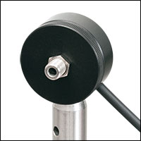
Figure 4.2 S120C and S120-SMA Fiber Adapter
Click to Expand
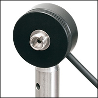
Figure 4.1 S120C and S120-FC Fiber Adapter
The compact design of Thorlabs' Standard Photodiode Sensors allows easy integration into existing setups. Typical mounting configurations including post, cage, and lens tube options are available. Shown on this page are several different choices for mounting these sensors.
The standard photodiode sensors are compatible with all S120-xx series fiber adapters. FC/PC and SMA adapters are shown in Figures 4.1 and 4.2. Adapters for FC/APC, SC, LC, and ST connections are also available.
Click to Expand
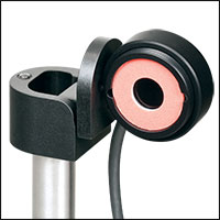
Figure 4.4 S120C and Flip Mount
Click to Expand
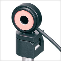
Figure 4.3 S120C and Flip Mount
Flip mounts are convenient for quick power measurements from a static location. The sensor can be placed in the path of the laser beam for the power measurement and flipped down during normal operation of the system.
FM90(/M) Right-Angle Flip Mounts are shown in Figures 4.3 and 4.4. Thorlabs also offers the TRB1(/M) Articulating Post Mount. The lockable articulating mount offers adjustable positioning of the sensor head.
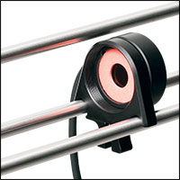
Click to Expand
Figure 4.6 S120C and QRC1A
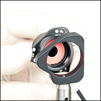
Click to Expand
Figure 4.5 S120C and KB1P
The standard photodiode sensors also feature externally SM1-threaded connections on the front face. The SM1 threading provides easy mounting to 1" lens tube systems and quick-release mounts.
Shown in Figures 4.5 and 4.6 are the KB1P(/M)
Note: Due to the thickness of the S12xC sensor, the QRC1A and CP44F (shown below) quick-release mounts can only be fully removed from the cage system by backing them off an open end. The two mounts are easily removed from the cage system if only three cage rods are used; see Figure 4.6.

Click to Expand
Figure 4.7 S120C and CP44F
Thorlabs also offers the CP44F 30 mm Cage Plates with Quick-Release Mounts. These mounts feature magnetically coupled front and back plates for easy and repeatable mounting.
Note: Like the QRC1A, the CP44F cannot be removed from a closed cage system.
Slim Photodiode Sensor Mounting Options
Click to Expand
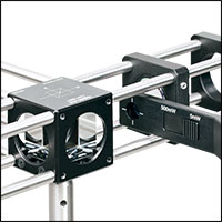
Figure 4.8 S130C Sensor in a 30 mm Cage
Thorlabs' Slim Photodiode Sensors are designed to fit into space-restricted environments such as 30 mm cage systems and optic-dense free-space arrangements.
Shown in Figure 4.8 is a S130C Sensor inserted into a 30 mm cage system. The application shown highlights the ease with which the sensor can be inserted into the cage, and the minimal space needed to take a power measurement.
The slim photodiode sensors may also be mounted on a TRB1(/M) Articulating Mount. This mount allows repeatable insertion of the sensor into tight optic arrangements. After the measurement is made, the sensor may be rotated out of the beam path for normal operation.
Compact Slim Photodiode Sensor Mounting Options

Click to Expand
Figure 4.9 S116C Sensor in a 16 mm Cage
Thorlabs' Compact Slim Photodiode Sensors are designed to fit into even tighter spaces such as 16 mm cage systems, our slotted Ø1/2" lens tubes, and other optic-dense free-space arrangements.
Shown in Figure 4.9 is a S116C Sensor inserted into a 16 mm cage system. The application shown highlights the ease with which the sensor can be inserted into the cage, and the minimal space needed to take a power measurement.
The compact slim photodiode sensor has two 8-32 (M4) taps for post mounting. One tap mounts the sensor horizontally, as seen in Figure 4.9, and one allows it to be mounted vertically. The sensor may also be mounted on a TRB1(/M) Articulating Mount. This mount allows repeatable insertion of the sensor into tight optic arrangements. After the measurement is made, the sensor may be rotated out of the beam path for normal operation.
Microscope Slide Photodiode Sensor Mounting Options

S170C Mounted on a Post
Figure 4.11 The S170C may be post mounted via the 8-32 (M4 x 0.7) tap in the side of the housing.

Click to Expand
Figure 4.10 S170C in a Microscope Slide Holder
Thorlabs' Microscope Slide Power Sensors are designed so they can be mounted directly in a microscope slide holder. The 76.0 mm x 25.2 mm x 5.0 mm sensor head has the same footprint as a standard microscope slide and is compatible with most standard upright and inverted microscopes. Figure 4.10 shows the S170C power sensor flipped over so that the engraved back of the housing can be used for alignment.
The S170C and NS170C power sensors also have an 8-32 (M4 x 0.7) tap for post mounting. In Figure 4.11, an RA90(/M) Right-Angle Clamp is used with two Ø1/2" posts to mount the S170C sensor head in a horizontal orientation.
Integrating Sphere Photodiode Sensor Mounting Options
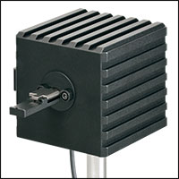
Click to Expand
Figure 4.13 S140C and S140-BFA Fiber Adapter
Click to Expand
Figure 4.12 S140C and S120-FC Fiber Adapter
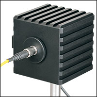
Thorlabs' Integrating Sphere Photodiode Sensors provide a low-loss cavity for diverging, non-uniform, or off-axis beam measurements. These integrating spheres are ideal for all fiber-based applications due to the beam divergence at the end of the fiber.
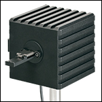
Shown in Figure 4.12 is an S140C Integrating Sphere with an S120-FC Fiber Adapter and shown in Figure 4.13 is an S140C with an S140-BFA Bare Fiber Adapter. The bare fiber adapter features a mounting clamp and light shield to decrease interference from ambient light.
Compact Fiber Photodiode Sensor Mounting Options
Click to Expand
Figure 4.15 PM100D2 with S150C Sensor

Click to Expand
Figure 4.14 S150C Sensor with FC and SMA Connectors
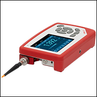
Thorlabs' Compact Fiber Photodiodes are the ideal choice for a portable, fiber-coupled power meter. The S15xC sensors are compatible with a wide variety of fiber connections. PM20-xx adapters are available to couple FC, APC, SMA, ST, SC, and LC connectors with the sensors. Shown in Figure 4.14 is an S150C Sensor with FC and SMA connector adapters.
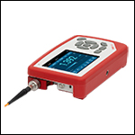
Shown in Figure 4.15 is a PM100D2 console with an S150C sensor connected to an FC connectorized optical fiber. This setup is ideal for portable use in the lab or in the field.
PULSE CALCULATIONS
Pulsed Laser Emission: Power and Energy Calculations
Determining whether emission from a pulsed laser is compatible with a device or application can require referencing parameters that are not supplied by the laser's manufacturer. When this is the case, the necessary parameters can typically be calculated from the available information. Calculating peak pulse power, average power, pulse energy, and related parameters can be necessary to achieve desired outcomes including:
- Protecting biological samples from harm.
- Measuring the pulsed laser emission without damaging photodetectors and other sensors.
- Exciting fluorescence and non-linear effects in materials.
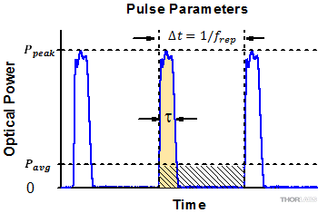
Pulsed laser radiation parameters are illustrated in Figure 170A and described in Table 170B. For quick reference, a list of equations is provided below. The document available for download provides this information, as well as an introduction to pulsed laser emission, an overview of relationships among the different parameters, and guidance for applying the calculations.
|
Equations: |
||||
 |
and |  |
||
 |
||||
 |
||||
 |
||||
Peak power and average power calculated from each other: |
||||
 |
and |  |
||
| Peak power calculated from average power and duty cycle*: | ||||
 |
*Duty cycle ( ) is the fraction of time during which there is laser pulse emission. ) is the fraction of time during which there is laser pulse emission. |
|||
Click to Enlarge
Figure 170A Parameters used to describe pulsed laser emission are indicated in this plot and described in Table 170B. Pulse energy (E) is the shaded area under the pulse curve. Pulse energy is, equivalently, the area of the diagonally hashed region.
| Table 170B Pulse Parameters | |||||
|---|---|---|---|---|---|
| Parameter | Symbol | Units | Description | ||
| Pulse Energy | E | Joules [J] | A measure of one pulse's total emission, which is the only light emitted by the laser over the entire period. The pulse energy equals the shaded area, which is equivalent to the area covered by diagonal hash marks. | ||
| Period | Δt | Seconds [s] | The amount of time between the start of one pulse and the start of the next. | ||
| Average Power | Pavg | Watts [W] | The height on the optical power axis, if the energy emitted by the pulse were uniformly spread over the entire period. | ||
| Instantaneous Power | P | Watts [W] | The optical power at a single, specific point in time. | ||
| Peak Power | Ppeak | Watts [W] | The maximum instantaneous optical power output by the laser. | ||
| Pulse Width |  |
Seconds [s] | A measure of the time between the beginning and end of the pulse, typically based on the full width half maximum (FWHM) of the pulse shape. Also called pulse duration. | ||
| Repetition Rate | frep | Hertz [Hz] | The frequency with which pulses are emitted. Equal to the reciprocal of the period. | ||
Example Calculation:
Is it safe to use a detector with a specified maximum peak optical input power of 75 mW to measure the following pulsed laser emission?
- Average Power: 1 mW
- Repetition Rate: 85 MHz
- Pulse Width: 10 fs
The energy per pulse:

seems low, but the peak pulse power is:

It is not safe to use the detector to measure this pulsed laser emission, since the peak power of the pulses is >5 orders of magnitude higher than the detector's maximum peak optical input power.
CONSOLE SELECTION
Thorlabs offers a wide selection of power and energy meter consoles and interfaces for operating our power and energy sensors. Key specifications of all of our power meter consoles and interfaces are presented in this tab to help you decide which device is best for your application. We also offer self-contained wireless power meters and compact USB power meters.
When used with our C-series sensors, Thorlabs' power meter consoles and interfaces recognize the type of connected sensor and measure the current or voltage as appropriate. Our C-series sensors have responsivity calibration data stored in their connectors. The console will read out the responsivity value for the user-entered wavelength and calculate a power or energy reading.
- Photodiode sensors deliver a current that depends on the input optical power and the wavelength. The current is fed into a transimpedance amplifier, which outputs a voltage proportional to the input current. The photodiode's responsivity is wavelength dependent, so the correct wavelength must be entered into the console for an accurate power reading. The console reads out the responsivity for this wavelength from the connected sensor and calculates the optical power from the measured photocurrent.
- Thermal sensors deliver a voltage proportional to the input optical power. Based on the measured sensor output voltage and the sensor's responsivity, the console will calculate the incident optical power.
- Thermal position and energy sensors incorporate four thermopiles arranged as quadrants of a square. By comparing the voltage output from each quadrant, the unit calculates the beam's position.
- Energy sensors are based on the pyroelectric effect. They deliver a voltage peak proportional to the pulse energy. If an energy sensor is recognized, the console will use a peak voltage detector, and the pulse energy will be calculated from the sensor's responsivity.
The consoles and interfaces are also capable of providing a readout of the current or voltage delivered by the sensor. Select models also feature an analog output.
Consoles
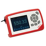
| Item # | PM100A | PM100D2 | PM100D3 | PM400 | PM5020 |
|---|---|---|---|---|---|
| (Click Photo to Enlarge) |  |
 |
 |
 |
 |
| Sensor Compatibility (Sensors Not Included) | |||||
| Photodiode Power |  |
 |
 |
 |
 |
| Thermal Power |  |
 |
 |
 |
 |
| Thermal Position & Power | - | - |  |
 |
 |
| Pyroelectric Energy | - |  |
 |
 a a |
 |
| Key Features | |||||
| Housing Dimensions (H x W x D) |
7.24" x 4.29" x 1.61" (184 mm x 109 mm x 41 mm) |
6.42" x 3.87" x 1.38" (163.0 mm x 98.4 mm x 35.0 mm) |
5.35" x 3.78" x 1.16" (136.0 mm x 96.0 mm x 29.5 mm) |
9.97" x 4.35" x 11.56" (253.2 mm x 110.6 mm x 293.6 mm) |
|
| Channels | 1 | 2 | |||
| External Temperature Sensor Input (Sensor Not Included) | - | - | Readout and Record Temperature Over Time | ||
| External Humidity Sensor Input (Sensor Not Included) | - | - | Readout and Record Humidity Over Time | ||
| Analog Outputb | Amplified Input Signal, SMA, 0 to 2 V, Up to 100 kHz |
Amplified Input Signal or 12-bit DAC Corrected Input Signal, SMA, 0 to 2.5 V, Up to 100 kHz |
Amplified Input Signal, 12-bit DAC Corrected Input Signal, or 14-bit DAC Corrected X-Y Position Signal, SMA, 0 to 2.5 V (Power); -2.0 to 2.0 V (Position), Up to 100 kHz |
Amplified Input Signal or DAC Corrected Input Signal, 2p Audio 3.5 mm (Adapter to BNC included), 0 to 2 V, Up to 100 kHz |
Amplified Input Signal or DAC Corrected Input Signal, 2 x BNC, -2.5 to 10 V, Up to 250 kHz. Programmable AOc, 4 x BNC, -5 to 10 V, Up to 1 kHz |
| Input/Output Ports | - | 26-Pin AUX Connector With 4 GPIO, AN OUT for Power (Analog Input Signal and 12-bit DAC) and Position Sensor (14-bit DAC), I2C, UART, and Analog and Digital Supply Voltages | 14-Pin AUX Connector With 4 GPIO, Programmable, 2 x 10 bit ADC for External Temperature, Relative Humidity Sensor, +3.3 V, ±2.5 V (100 mA Max) |
10-Pin PCB Connector, 4 Configurable Digital I/O Channels, 1 Trigger In/Out, I2C (LVTTL / TTL) |
|
| Shutter Control | - | - | - | - | Support for SH05R(/M) or SH1(/M) Optical Shutter with Interlock Input |
| Fan Control | - | - | - | - | |
| Source Spectral Correction | - | ||||
| Attenuation Correction | - | ||||
| External Trigger Input | - | - | - | ||
| Display | |||||
| Type | Mechanical Needle and LCD Display with Digital Readout | 3.5" Full Color Touchscreen Display, 640 x 480 Pixels | 4.3" Protected Capacitive Touchscreen with Color Display, 400 x 272 Pixels | 5" IPS Touchscreen LCD Display, 854 x 480 Pixels | |
| Dimensions | Digital: 1.9" x 0.5" (48.2 mm x 13.2 mm) Analog: 3.54" x 1.65" (90.0 mm x 42.0 mm) |
2.80" x 2.10" (71.0 mm x 53.3 mm) |
3.7" x 2.1" (95 mm x 54 mm) |
4.32" x 2.43" (109.7 mm x 61.6 mm) |
|
| Refresh Rate | 20 Hz | 50 Hz | 10 Hz (Numerical) 25 Hz (Analog Simulation) |
25 Hz | |
| Measurement Viewsd | |||||
| Numerical | |||||
| Mechanical Analog Needle | - | - | - | - | |
| Simulated Analog Needle | - | ||||
| Bar Graph | - | ||||
| Trend Graph | - | ||||
| Statistics | |||||
| Pass/Fail | - | - | - | - | |
| Scope | - | - | - | ||
| Memory | |||||
| Type | - | eMMC Flash | NAND Flash | SD Card | |
| Size | - | 8 GB | 4 GB | 8 GB | |
| Power | |||||
| Battery | LiPo 3.7 V 2300 mAh | LiPo 3.7 V 2300 mAh | LiPo 3.7 V 2300 mAh | - | |
| External | 5 VDC via USB or Included AC Adapter | 5 VDC via USB-C Connector | 5 VDC via USB Mini B Connector | Line Voltage: 100 - 240 V | |
Interfaces
| Item # | PM101 | PM102 | PM103 | PM101A | PM102A | PM103A |
|---|---|---|---|---|---|---|
| (Click Photo to Enlarge) |  |
 |
 |
 |
 |
 |
| Operation Protocol | USB, RS232, UART, and Analog |
USB and Analog SMA | ||||
| Sensor Compatibility | ||||||
| Photodiode |  |
- |  |
 |
- |  |
| Thermal Power |  |
 |
- |  |
 |
- |
| Thermal Position & Power | - |  |
- | - |  |
- |
| Pyroelectric | - | - |  |
- | - |  |
| Item # | PM103E | PM101R | PM101U | PM102U | PM103U | PM100USB | |
|---|---|---|---|---|---|---|---|
| (Click Photo to Enlarge) |  |
 |
 |
 |
 |
 |
|
| Operation Protocol | Ethernet, RS232, and Analog | USB and RS232 |
USB Operation | USB | |||
| Sensor Compatibility | |||||||
| Photodiode |  |
 |
- |  |
 |
||
| Thermal Power |  |
 |
 |
- |  |
||
| Thermal Position & Power | - | - |  |
- | - | ||
| Pyroelectric | - | - | - |  |
 a a |
||
SENSOR SELECTION

Click to Enlarge
Figure 113A The PM160 wireless power meter, shown here with an iPad mini (not included), can be remotely operated using Apple mobile devices.
This tab outlines the full selection of Thorlabs' power and energy sensors. Refer to Table 113B for power meter console and interface compatibility information.
In addition to the power and energy sensors listed below, Thorlabs also offers all-in-one, wireless, handheld power meters and compact USB power meter interfaces that contain either a photodiode or a thermal sensor, as well as power meter bundles that include a console, sensor head, and post mounting accessories.
Thorlabs offers four types of sensors:
- Photodiode Sensors: These sensors are designed for power measurements of monochromatic or near-monochromatic sources, as they have a wavelength dependent responsivity. These sensors deliver a current that depends on the input optical power and the wavelength. The current is fed into a transimpedance amplifier, which outputs a voltage proportional to the input current.
- Thermal Sensors: Constructed from material with a relatively flat response function across a wide range of wavelengths, these thermopile sensors are suitable for power measurements of broadband sources such as LEDs and SLDs. Thermal sensors deliver a voltage proportional to the input optical power.
- Thermal Position & Power Sensors: These sensors incorporate four thermopiles arranged as quadrants of a square. By comparing the voltage output from each quadrant, the unit calculates the beam's position.
- Pyroelectric Energy Sensors: Our pyroelectric sensors produce an output voltage through the pyroelectric effect and are suitable for measuring pulsed sources, with a repetition rate limited by the time constant of the detector. These sensors will output a peak voltage proportional to the incident pulse energy.
| Table 113B Console Compatibility | |||||||||
|---|---|---|---|---|---|---|---|---|---|
| Console Item # | PM100A | PM100D2 | PM100D3 | PM400 | PM5020 | PM101 Series |
PM102 Series |
PM103 Series |
PM100USB |
| Photodiode Power |  |
 |
 |
 |
 |
 |
- |  |
 |
| Thermal Power |  |
 |
 |
 |
 |
 |
 |
- |  |
| Thermal Position | - | - |  |
 |
 |
- |  |
- | - |
| Pyroelectric Energy | - |  |
 |
 a a |
 |
- | - |  |
 a a |
Power and Energy Sensor Selection Guide
There are two options for comparing the specifications of our Power and Energy Sensors. Tables 113C, 113D, 113E, and 113F sort our sensors by type (e.g., photodiode, thermal, or pyroelectric) and provide key specifications.
Alternatively, the selection guide Figures 113G and 113H arrange our entire selection of photodiode and thermal power sensors by wavelength (Figure 113G) or optical power range (Figure 113H). Each box contains the item # and specified range of the sensor. These graphs allow for easy identification of the sensor heads available for a specific wavelength or power range.
| Table 113C Photodiode Power Sensors |
|---|
| Table 113D Thermal Power Sensors |
|---|
| Table 113E Thermal Position & Power Sensors |
|---|
| Table 113F Pyroelectric Energy Sensors |
|---|

 Figure 113G Sensor Options Arranged by Wavelength Range
 Figure 113H Sensor Options Arranged by Power Range
RECALIBRATION
Figure 796A DAkkS-accredited calibrations are performed in accordance with DIN EN ISO/IEC 17025:2018.
Recalibration Services
Thorlabs offers two types of recalibration services in-house for our power and energy meter electronics and photodiode power sensors: ISO 17025 accredited calibrations and manufacturer calibrations. Only the manufacturer calibration is available for the NS170C microscope slide peak power sensor, our thermal power sensors, and our pyroelectric energy sensors. All new products are delivered with a manufacturer calibration by default; if an ISO 17025 accredited calibration is desired for a new device, please contact Tech Sales.
ISO 17025 accredited calibrations are performed in-house in accordance with DIN EN ISO/IEC 17025:2018. Thorlabs GmbH's calibration laboratory is accredited by the German Accreditation Body (DAkkS), the national accreditation authority of the Federal Republic of Germany. The scope of services is described here in English or German. Accredited calibrated power and/or energy meter electronics come with a dedicated certificate of calibration proving the specified accuracy and traceability of calibration data. This certification may be required in certain applications or industries, such as the medical market.
In contrast, our manufacturer calibrations are subject to the quality management requirements of ISO 9001. The certificate of calibration lists the equipment used for the calibration procedure as well as the calibration data acquired. The manufacturer calibration of a power sensor includes recalibration of a single-channel console or interface at no additional cost. If you wish to calibrate one or more sensors with a dual-channel console, each sensor and console calibration service will need to be purchased individually.
Both types of calibration can be offered for third-party equipment or adjusted for special requirements upon request. Please reach out to Tech Sales for further details.
We recommend recalibrating your Thorlabs sensor and console as a pair; however, each may be recalibrated individually. To ensure accurate measurements, we recommend recalibrating annually. To order one or more sensor recalibrations with a dual-channel console, we offer two options: either 1) fill out the Returns Material Authorization (RMA) form with each console and sensor Item # to be recalibrated and specify either manufacturer calibration or ISO 17025 accredited calibration in the "Further Details" field, or 2) separately add each recalibration service Item # offered below to your cart.
Standard Photodiode Power Sensors
Click to Enlarge
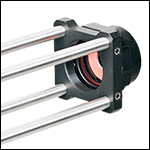
Figure G1.1 S120C and CP44F Quick-Release Mount
- For General Purpose Optical Power Measurements
- Integrated Viewing Target for Easy Sensor Alignment
- Ø9.5 mm Sensor Aperture
- Sensor, Protective Cap, and IR Target Included
- Fiber Adapters Available Separately (See Table G1.2)
The S12xC Standard Photodiode Power Sensors are ideal for metering low power coherent and incoherent sources from the UV to the NIR. These sensors feature an integrated viewing target for easy alignment, enhanced shielding against electromagnetic interference, an over-temperature alert device, and large Ø9.5 mm sensor aperture. The sensors are compatible with Ø1/2" posts and SM1 (1.035"-40) lens tubes and are ideal for free-space and fiber-coupled sources. They may also be mounted in 30 mm cage systems using our selection of 30 mm Cage System Optic Mounts with internal SM1 threading.
Each sensor is shipped with NIST- or PTB-traceable calibration data. The included data will match the calibration certification of the photodiode used to test the individual sensor. Thorlabs offers recalibration services for these photodiode power sensors, which can be ordered below (see Item #s CAL-UVPD or CAL-UVPDD for UV-extended Si sensors, Item #s CAL-PD or CAL-PDD for Si sensors and Item #s CAL-IRPD or CAL-IRPDD for Ge sensors).
| Table G1.2 Specifications | ||||
|---|---|---|---|---|
| Item #a | S120VC | S120C | S121C | S122Cb,i |
| Sensor Image (Click the Image to Enlarge) |
||||
| Aperture Size | Ø9.5 mm | |||
| Wavelength Range | 200 nm - 1100 nm | 400 nm - 1100 nm | 400 nm - 1100 nm | 700 nm - 1800 nm |
| Power Range | 50 nW - 50 mW (200 nm - 450 nm) 50 nW - 20 mW (450 nm - 1100 nm) |
50 nW - 50 mW | 500 nW - 500 mW | 50 nW - 40 mW |
| Detector Type | Si Photodiode (UV Extended) | Si Photodiode | Ge Photodiode | |
| Linearity | ±0.5% | |||
| Resolutionc | 1 nW | 10 nW | 2 nW | |
| Measurement Uncertaintyd | ±3% (440 nm - 980 nm) ±5% (280 nm - 439 nm) ±7% (200 nm - 279 nm, 981 nm - 1100 nm) |
±3% (440 nm - 980 nm) ±5% (400 nm - 439 nm) ±7% (981 nm - 1100 nm) |
±5% | |
| Responsivitye (Click for Plot) | Raw Data |
Raw Data |
Raw Data |
Raw Data |
| Coating/Diffuser | Reflective ND (OD1.5)f | Reflective ND (OD1)g | Reflective ND (OD2)h | Absorptive ND (Schott NG9) |
| Head Temperature Measurement | NTC Thermistor 4.7 kΩ | |||
| Housing Dimensions | Ø30.5 mm x 12.7 mm | |||
| Active Detector Area | 9.7 mm x 9.7 mm | |||
| Cable Length | 1.5 m | |||
| Mounting Threadf,g,h | Universal 8-32 / M4 Tap, Post Not Included | |||
| Aperture Thread | External SM1 (1.035"-40) | |||
| Fiber Adapters | S120-FC2, S120-FC, S120-APC2, S120-APC, S120-SMA, S120-ST, S120-LC, S120-SC, and S120-25 (Not Included) | |||
| Compatible Consoles | PM100A, PM100D2, PM100D3, PM400, and PM5020 | |||
| Compatible Interfaces | PM101, PM101A, PM101R, PM101U, PM103, PM103E, PM103A, PM103U, and PM100USB | |||
Part Number | Description | Price | Availability |
|---|---|---|---|
S120VC | Standard Photodiode Power Sensor, UV-Extended Si, 200 - 1100 nm, 50 nW - 50 mW | $528.76 | Lead Time |
S120C | Standard Photodiode Power Sensor, Si, 400 - 1100 nm, 50 nW - 50 mW | $381.34 | In Stock Overseas |
S121C | Standard Photodiode Power Sensor, Si, 400 - 1100 nm, 500 nW - 500 mW | $414.38 | Lead Time |
S122C | Standard Photodiode Power Sensor, Ge, 700 - 1800 nm, 50 nW - 40 mW | $761.37 | Lead Time |
Slim Photodiode Power Sensors

Click for Details
- For Optical Power Measurements in Confined Spaces
- Slim Design: 5 mm Thin on Sensor Side
- Ø9.5 mm Sensor Aperture
- Slideable ND Filter Automatically Changes Sensor Power Range
- Accessories Available Separately Below:
- SM1A29 Adapter with VIS/IR Target and External SM1 Threading
- FBSM Mount with VIS/IR Target for FiberBench Systems
The S13xC Slim Photodiode Power Sensors are designed to take optical source power measurements in locations where space and accessibility are at a premium. The 5 mm thin
Slim Photodiode Sensors can fit between closely spaced optics, cage systems, and other arrangements where standard power meters may not fit. These sensors also feature a large Ø9.5 mm sensor aperture and slideable neutral density filter for dual power ranges in one compact device.
A separately available SM1A29 adapter can be attached by two setscrews to any S130 series power sensor to mount fiber adapters, light shields, filters or any other SM1-threaded (1.035"-40) mechanics or optics. The FBSM Mount allows our S130 series power sensors to be mounted vertically into FiberBench systems for stable mounting with a minimal footprint.
Each sensor is shipped with NIST- or PTB-traceable calibration data. The included data will match the calibration certification of the photodiode used to test the individual sensor. Thorlabs offers recalibration services for these photodiode power sensors, which can be ordered below (see Item #s CAL-UVPD2 or CAL-UVPD2D for UV-extended Si sensors, Item #s CAL-PD2 or CAL-PD2D for Si sensors, and Item #s CAL-IRPD2 or CAL-IRPD2D for Ge sensors).
| Item #a | S130VC | S130C | S132Cb | ||
|---|---|---|---|---|---|
| Sensor Image (Click the Image to Enlarge) |
|||||
| Aperture Size | Ø9.5 mm | ||||
| Wavelength Range | 200 nm - 450 nm | 450 nm - 1100 nm | 400 nm - 1100 nm | 700 nm - 1800 nmc | |
| Power Range (with Filter) |
500 pW - 0.5 mW (Up to 50 mW)d |
500 pW - 0.2 mW (Up to 20 mW)d |
500 pW - 5 mW (Up to 500 mW) |
5 nW - 5 mW (Up to 500 mW) |
|
| Detector Type | Si Photodiode (UV Extended) | Si Photodiode | Ge Photodiode | ||
| Linearity | ±0.5% | ||||
| Resolution | 100 pWe | 1 nWf | |||
| Measurement Uncertaintyg | ±3% (440 nm - 980 nm) ±5% (280 nm - 439 nm) ±7% (200 nm - 279 nm, 981 nm - 1100 nm) |
±3% (440 nm - 980 nm) ±5% (400 nm - 439 nm) ±7% (981 nm - 1100 nm) |
±5% | ||
| Responsivityh (Click for Plot) | Raw Data |
Raw Data |
Raw Data |
||
| Coating/Diffuser | Reflective ND (OD1.5)d | Reflective ND (OD2)i | Absorptive ND (Schott NG9/KG3)c | ||
| Housing Dimensions | 150 mm x 19 mm x 10 mm; 5 mm Thickness on Sensor Side | ||||
| Active Detector Area | 9.7 mm x 9.7 mm | ||||
| Cable Length | 1.5 m | ||||
| Mounting Thread | Separate 8-32 and M4 Taps, Posts Not Included | ||||
| Adapters (Not Included) | SM1A29: Add SM1 Thread and Viewing Target to Aperture Fiber Adapters Compatible with SM1A29 Adapter: S120-FC2, S120-FC, S120-APC2, S120-APC, S120-SMA, S120-ST, S120-LC, S120-SC, and S120-25 FBSM: Integrate Sensor into FiberBench Setups |
||||
| Compatible Consoles | PM100A, PM100D2, PM100D3, PM400, and PM5020 | ||||
| Compatible Interfaces | PM101, PM101A, PM101R, PM101U, PM103, PM103A, PM103E, PM103U, and PM100USB | ||||
Part Number | Description | Price | Availability |
|---|---|---|---|
S130VC | Slim Photodiode Power Sensor, UV-Extended Si, 200 - 1100 nm, 500 pW - 0.5 mW, Up to 50 mW with Filter | $767.74 | Today |
S130C | Slim Photodiode Power Sensor, Si, 400 - 1100 nm, 500 pW - 5 mW, Up to 500 mW with Filter | $634.26 | Today |
S132C | Slim Photodiode Power Sensor, Ge, 700 - 1800 nm, 5 nW - 5 mW, Up to 500 mW with Filter | $901.20 | Lead Time |
SM1A29 | Customer Inspired! SM1 Thread Adapter for Slim Photodiode Sensors | $52.44 | In Stock Overseas |
FBSM | FiberBench Mount for Slim Photodiode Sensors | $52.10 | In Stock Overseas |
Compact Slim Photodiode Power Sensor
| Item #a | S116C | |
|---|---|---|
| Sensor Image (Click the Image to Enlarge) |
||
| Aperture Size | Ø6 mm | |
| Wavelength Range | 400 nm - 1100 nm | |
| Power Range | 20 nW - 50 mW | |
| Detector Type | Si Photodiode | |
| Linearity | ±0.5% | |
| Resolution | 1 nWb | |
| Measurement Uncertaintyc | ±3% (440 nm - 980 nm) ±5% (400 nm - 439 nm) ±7% (981 nm - 1100 nm) |
|
| Responsivityd (Click for Plot) |
Raw Data |
|
| Coating/Diffuser | Absorptive ND (NG9) | |
| Housing Dimensions (L x W x T) |
70.0 mm x 11.0 mm x 8.9 mm; 10.0 mm Width and 4.5 mm Thickness on Sensor Side |
|
| Active Detector Area | 7 mm x 7 mm | |
| Cable Length | 1.5 m | |
| Mounting Threads | 2 Universal 8-32 / M4 Taps (One on the Back, One on the Bottom), Posts Not Included |
|
| Adapters (Not Included) |
SM05A29: Add SM05 Thread to Aperture Fiber Adapters Compatible with SM05A29 Adapter: PM20-FC2, PM20-FC, PM20-APC2, PM20-APC, PM20-SMA, PM20-ST, PM20-SC, and PM20-LC, and PM20-25 |
|
| Compatible Consoles | PM100A, PM100D2, PM100D3, PM400, and PM5020 | |
| Compatible Interfaces | PM101, PM101A, PM101R, PM101U, PM103, PM103A, PM103E, PM103U, and PM100USB | |
- For Optical Power Measurements in Tiny Spaces Such as 16 mm Cage Systems
- Wavelength Range: 400 nm - 1100 nm
- Very Slim Design: 10.0 mm Wide and 4.5 mm Thin on Sensor Side
- Silicon Photodiode with Ø6 mm Sensor Aperture
- Designed for Power Measurements for Low Power Lasers
- Post Mountable via 8-32 (M4) Taps
- SM05A29 Adapter with External SM05 (0.535"-40) Threading Available Separately Below
The S116C Compact Slim Photodiode Power Sensor is designed to take optical source power measurements in locations where space and accessibility are at a premium. The 4.5 mm thin photodiode sensor can fit between the rods of a 16 mm cage system, as seen in Figure G3.2, as well as through the side openings of our slotted Ø1/2" lens tubes (Item #s SM05L20C and SM05L30C). This sensor also features a Ø6 mm sensor aperture.
A separately available SM05A29 adapter can be attached by two 0.05" (1.3 mm) hex setscrews to an S116C power sensor to mount fiber adapters, light shields, filters or any other SM05-threaded (0.535"-40) mechanics or optics. The adapter mounted on the S116C power sensor is shown in Figure G3.1.
Each sensor is shipped with NIST- and PTB-traceable calibration data. The included data is determined with the help of a certified reference diode, which corresponds to the spectral range of the sensor to be calibrated. Thorlabs offers recalibration services for these photodiode power sensors, which can be ordered below (see Item #s CAL-PD or CAL-PDD for Si sensors).

Click for Details
Figure G3.1 SM05A29 SM05 Thread Adapter (Sold Separately) Mounted on
an S116C Sensor
Part Number | Description | Price | Availability |
|---|---|---|---|
S116C | Compact Slim Photodiode Power Sensor, Si, 400 - 1100 nm, 20 nW - 50 mW | $469.85 | Today |
SM05A29 | SM05-Threaded Adapter for Compact Slim Photodiode Sensors | $49.33 | In Stock Overseas |
Microscope Slide Photodiode Power Sensors

Click for Details
Figure G4.1 Using the engraved alignment target on the back of the sensor housing, a user can position the stage so that when the sensor is flipped, the beam strikes the center of the sensor. The S170C sensor is shown in this image.
- Designed to Measure Optical Power at the Sample Plane of a Microscope
- Silicon Photodiode with Large 18 mm x 18 mm Active Area
- Sensor Housing Dimensions: 76.0 mm x 25.2 mm x 5.0 mm
- Novel Optical Design Accommodates High NA Objectives
- Information Stored in Connector
- Sensor Data
- NIST- and PTB-Traceable Calibration Data
- Post Mountable via 8-32 (M4 x 0.7) Tap
The Microscope Slide Power Sensor Heads with silicon photodiodes are designed to measure the power at the sample plane in microscopy setups. The S170C sensor can detect wavelengths from 350 nm to 1100 nm at optical powers from 10 nW to 150 mW. The NS170C sensor is designed to measure the relative peak power of femtosecond lasers with center wavelengths from 780 nm to 1300 nm and average powers from 0.5 mW to 350 mW. Each sensor head's
76.0 mm x 25.2 mm footprint matches that of a standard microscope slide and is compatible with most standard upright and inverted microscopes.
The photodiode used in the S170C sensor has 18 mm x 18 mm active area and is contained in a sealed housing behind a neutral density (ND) filter. A 20 mm x 20 mm indentation around the surface of the ND filter is sized to accept standard microscope cover slips. An immersion medium (water, glycerol, oil) may be placed in this well directly over the ND filter, or a cover slip may be inserted first to simplify clean up. The gap between the photodiode and the neutral density filter has been filled with an index matching gel in order to prevent internal reflections from causing significant measurement errors when using high NA objectives with oil or water.
The NS170C sensor is designed to measure the relative peak power of two-photon lasers by utilizing a second-order nonlinear β-BBO crystal to convert incident ultrafast NIR pulses into their visible second harmonic. Shortpass filters underneath the β-BBO crystal reject the residual NIR light, allowing only the second harmonic light to transmit down to a large area silicon photodiode sensor. At the entrance of the sensor is a 170 µm thick cover glass sealed to the sensor housing, allowing the sensor to be used with dry, water immersion, and oil immersion objectives. The working distance from the top of the cover glass to the β-BBO crystal is 0.22 mm.
The bottom of each sensor housing features a laser-engraved grid to aid in aligning and focusing the beam. In standard microscopes, this grid can be used for beam alignment before flipping the sensor head to face the objective for power measurements. In inverted microscopes, turn on the transmitted illuminator to align the grid on the detector housing with the beam, thereby centering the sensor in front of the objective. Alternatively, the diffusive surface of the ND filter can be used as a focusing plane.
To avoid damaging the sensor, we recommend positioning it in the light path at a location where the beam is not focused. It is important not to exceed the Max Average Power Density over the beam's spot size for the S170C sensor, and the Max Peak Power Density for the NS170C sensor (see Specs tab).
Each sensor is shipped with NIST- or PTB-traceable calibration data. The included data will match the calibration certification of the photodiode used to test the individual sensor. Sensor specifications and the included NIST- or PTB-traceable calibration data are stored in non-volatile memory in the sensor connector and can be read out by the latest generation of Thorlabs power meters. Please note that the NS170C sensor's NIST and PTB calibration is for the visible light incident on the detector; however, the magnitude of that visible light is specific to the illumination conditions of the NIR femtosecond pulses. We recommend yearly recalibration to ensure accuracy and performance, which can be ordered below (see Item #s CAL-PD or CAL-PDD for the S170C sensor, and Item # CAL-NS for the NS170C sensor). Please contact Tech Support for more information.
The complete set of specifications are presented on the Specs tab. Thorlabs also offers a Microscope Slide Sensor Head with a thermal sensor; the full presentation can be found here.
| Item #a | S170C | NS170C |
|---|---|---|
| Sensor Image (Click Image to Enlarge) |
 |
 |
| Dimensions | 76.0 mm x 25.2 mm x 5.0 mm (2.99" x 0.99" x 0.20") |
Base: 76.0 mm x 25.2 mm x 5.0 mm (2.99" x 0.99" x 0.20") Overall: 76.0 mm x 30.0 mm x 11.0 mm (2.99" x 1.18" x 0.43") |
| Active Detector Area | 18 mm x 18 mm | |
| Input Aperture | 20 mm x 20 mm | Ø4.5 mm |
| Wavelength Range | 350 nm - 1100 nm | Laser: 780 nm - 1300 nm SHG: 390 nm - 650 nm |
| Optical Power Working Range | 10 nW - 150 mW | Laser: 0.5 mW - 350 mWb SHG: 10 nW - 5 mW |
| Max Peak Power Densityc | - | 10 TW/cm2 |
| Detector Type | Silicon Photodiode | Second-Order Nonlinear Crystal with Silicon Photodiode |
| Linearity | ±0.5% | ±0.5%d |
| Resolution | 1 nWe | 1 nWd,e |
| Measurement Uncertaintyf | ±3% (440 nm - 980 nm) ±5% (350 nm - 439 nm) ±7% (981 nm - 1100 nm) |
±3% (440 nm - 650 nm)d ±5% (390 nm - 439 nm)d |
| Responsivityg (Click for Plot) |
Raw Data |
Raw Data |
| Neutral Density Filter | Reflective (OD 1.5) | N/A |
| Cable Length | 1.5 m | |
| Mounting Thread | Universal 8-32 / M4 x 0.7 Tap, Post Not Included | |
| Compatible Consoles | PM100A, PM100D2, PM100D3, PM400, and PM5020 | |
| Compatible Interfaces | PM101, PM101A, PM101R, PM101U, PM103, PM103A, PM103E, PM103U, and PM100USB | |
Part Number | Description | Price | Availability |
|---|---|---|---|
S170C | Customer Inspired! Microscope Slide Power Sensor, 350 - 1100 nm, 10 nW - 150 mW | $1,417.25 | Lead Time |
NS170C | Microscope Slide Peak Power Sensor for Two-Photon Lasers, 780 - 1300 nm | $2,835.50 | Today |
Integrating Sphere Photodiode Power Sensors
Click to Enlarge
Figure G5.2 S142C and S140-BFA Bare Fiber Adapter (Sold Separately)
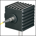
Click to Enlarge
Figure G5.1 S142C with the S120-FC Fiber Adapter (Included)
- For Measurements Independent of Beam Shape and Entrance Angle
- Integrating Sphere Design Acts as a Diffuser with Minimal Power Loss
- Ø5 mm, Ø7 mm, Ø12 mm, or Ø22 mm Input Sensor Aperture
- Spheres with Apertures ≤Ø12 mm Include a Removable S120-FC Fiber Adapter (FC/PC and FC/APC)
- Fiber Adapters for Terminated and Bare Fiber (See Table G5.4) are Compatible with Spheres with Apertures ≤Ø12 mm
These Integrating Sphere Photodiode Power Sensors are the ideal choice for power measurements independent of beam uniformity, divergence angle, beam shape, or entrance angle, making them excellent for use with fiber sources and off-axis free space sources. They feature enhanced shielding to avoid electromagnetic interference and an over-temperature alert sensor to warn against damage and measurement errors due to overheating of the sensor.
Our integrating spheres are designed for wavelength ranges from the visible through the NIR. Sensor heads for use between 350 and 2500 nm use a single Ø1" or Ø2" sphere made from Zenith® PTFE and feature a black housing to minimize reflected light around the entrance aperture. These sensors use either a silicon photodiode for detection in the 350 - 1100 nm range or an InGaAs photodiode for detection in the 800 - 1700 nm, 900 - 1650 nm, or 1200 - 2500 nm wavelength range.
The S180C integrating sphere for 2.9 - 5.5 µm uses two connected, gold-plated Ø20 mm spheres, with an entrance port in the first sphere and a port for the MCT (HgCdTe) detector located in the second sphere. Compared to single-sphere designs, the two-sphere configuration improves device sensitivity by minimizing the internal sphere surface area while still effectively shielding the detector from direct illumination. This design reduces the effect of input angle, divergence, and beam shape on the measurement result by effectively shielding the photodiode without the use of a baffle or other shielding mechanism.

Click to Enlarge
Figure G5.3 A baffle on the S142CL and S145CL spheres blocks light from directly hitting the detector.
The integrating spheres with Ø5 mm, Ø7 mm, or Ø12 mm apertures feature large active detector areas, and externally SM1-threaded (1.035"-40) adapters for compatibility with the included S120-FC fiber adapter. Because of the large active detector areas of these sensors, the included S120-FC fiber adapter can be used with FC/PC- or FC/APC-terminated fiber. The externally SM1-threaded adapter can be removed using a size 1 screwdriver to place components closer to the window.
The S142CL and S145CL integrating spheres feature a large Ø22 mm input aperture and a baffle within the sphere which prevents direct illumination of the photodiode. The large aperture and baffle enable measurements of large and divergent beams, such as those emitted from LED and VCSEL light sources. The input face of the detectors have four 4-40 threads for mounting 30 mm cage system components. Additionally, insertion of a second or third port in the sensor head is possible on request, please contact Tech Support for details.
Each sensor is shipped with NIST- or PTB-traceable calibration data. The included data will match the calibration certification of the photodiode used to test the individual sensor. NIST- or PTB-traceable data is stored in the sensor connector. Thorlabs offers recalibration services for these photodiode power sensors, which can be ordered below (see Item #s CAL-PD or CAL-PDD for Si sensors, Item #s CAL-IRPD or CAL-IRPDD for InGaAs sensors, Item # CAL-MIRPD for extended InGaAs or MCT sensors, or Item # CAL-MIRPDD for extended InGaAs sensors).
| Table G5.4 Specifications | ||||||||||
|---|---|---|---|---|---|---|---|---|---|---|
| Item #a | S140C | S142C | S142CL | S144C | S145C | S145CL | S146C | S148C | S180C | |
| Sensor Image (Click the Image to Enlarge) |
 |
 |
 |
 |
 |
 |
 |
 |
 |
|
| Aperture Size | Ø5 mm | Ø12 mm | Ø22 mm | Ø5 mm | Ø12 mm | Ø22 mm | Ø12 mm | Ø5 mm | Ø7 mm | |
| Wavelength Range | 350 nm - 1100 nm | 400 nm - 1100 nm | 800 nm - 1700 nm | 900 nm - 1650 nm | 1200 nm - 2500 nm | 2.9 µm - 5.5 µm | ||||
| Power Range | 1 µW - 500 mW | 1 µW - 5 W | 10 µW - 5 W | 1 µW - 500 mW | 1 µW - 3 W | 10 µW - 3 W | 10 µW - 20 W | 1 µW - 1 W | 1 µW - 3 W | |
| Detector Type | Si Photodiode | Si Photodiode with Baffle | InGaAs Photodiode | InGaAs Photodiode with Baffle | InGaAs Photodiode | Extended InGaAs Photodiode | MCT (HgCdTe) Photodiode |
|||
| Linearity | ±0.5% | |||||||||
| Resolutionb | 1 nW | 10 nW | 1 nW | 10 nW | 1 nW | 10 nW | ||||
| Measurement Uncertaintyc,d |
±3% (440 - 980 nm) ±5% (350 - 439 nm) ±7% (981 - 1100 nm) |
±3% (440 - 980 nm) ±5% (400 - 439 nm) ±7% (981 - 1100 nm) |
±5% | |||||||
| Responsivitye (Click for Plot) |
Raw Data |
Raw Data |
Raw Data |
Raw Data |
Raw Data |
Raw Data |
Raw Data |
Raw Data |
Raw Data |
|
| Integrating Sphere Material (Size) |
Zenith® PTFE (Ø1") |
Zenith® PTFE (Ø2") |
Zenith® PTFE (Ø1") |
Zenith® PTFE (Ø2") |
Zenith® PTFE (Ø1") |
Gold Plating (Two Ø20 mm Spheres) |
||||
| Head Temperature Measurement |
NTC Thermistor 4.7 kΩ | |||||||||
| Housing Dimensions |
Ø45 mm x 30.5 mm | 70 mm x 74 mm x 70 mm | Ø45 mm x 30.5 mm | 70 mm x 74 mm x 70 mm | Ø45 mm x 30.5 mm | 59.0 mm x 50.0 mm x 28.5 mm |
||||
| Active Detector Area | 3.6 mm x 3.6 mm | Ø2 mm | Ø3 mm | Ø1 mm | Ø1 mm | 1 mm x 1 mm | ||||
| Cable Length | 1.5 m | |||||||||
| Mounting Thread | Separate 8-32 and M4 Taps, Posts Not Included | Universal |
Separate |
Universal |
Separate |
Universal |
||||
| Aperture Thread | Included Adapter with SM1 (1.035"-40) External Thread | None | Included Adapter with SM1 (1.035"-40) External Thread | None | Included Adapter with SM1 (1.035"-40) External Thread | |||||
| Compatible Fiber Adapters |
S120-FC (Included) S120-FC2, S120-APC2, S120-APC, S120-SMA, S120-ST, S120-SC, S120-LC, S120-25, and S140-BFA (Not Included) |
None | S120-FC (Included) S120-FC2, S120-APC2, S120-APC, S120-SMA, S120-ST, S120-SC, S120-LC, S120-25, and S140-BFA (Not Included) |
None | S120-FC (Included) S120-FC2, S120-APC2, S120-APC, S120-SMA, S120-ST, S120-SC, S120-LC, S120-25, and S140-BFA (Not Included) |
|||||
| Compatible Consoles | PM100A, PM100D2, PM100D3, PM400, and PM5020 | |||||||||
| Compatible Interfaces | PM101, PM101A, PM101R, PM101U, PM103, PM103A, PM103E, PM103U, and PM100USB | |||||||||
Part Number | Description | Price | Availability |
|---|---|---|---|
S140C | Integrating Sphere Photodiode Power Sensor, Si, 350 - 1100 nm, 1 µW - 500 mW | $875.77 | Lead Time |
S142C | Integrating Sphere Photodiode Power Sensor, Si, 350 - 1100 nm, 1 µW - 5 W | $1,215.15 | Today |
S142CL | Customer Inspired! Large Aperture Integrating Sphere Photodiode Power Sensor, Si, 400 - 1100 nm, 10 µW - 5 W | $1,309.68 | Today |
S144C | Integrating Sphere Photodiode Power Sensor, InGaAs, 800 - 1700 nm, 1 µW - 500 mW | $1,028.31 | Lead Time |
S145C | Integrating Sphere Photodiode Power Sensor, InGaAs, 800 - 1700 nm, 1 µW - 3 W | $1,262.18 | Lead Time |
S145CL | Customer Inspired! Large Aperture Integrating Sphere Photodiode Power Sensor, InGaAs, 800 - 1700 nm, 10 µW - 3 W | $1,358.79 | Today |
S146C | Integrating Sphere Photodiode Power Sensor, InGaAs, 900 - 1650 nm, 10 µW - 20 W | $1,262.18 | Lead Time |
S148C | Customer Inspired! Integrating Sphere Photodiode Power Sensor, Extended InGaAs, 1200 - 2500 nm, 1 µW - 1 W | $1,056.27 | Today |
S180C | Integrating Sphere Photodiode Power Sensor, MCT (HgCdTe), 2.9 - 5.5 µm, 1 µW - 3 W | $4,592.40 | In Stock Overseas |
Fiber Photodiode Power Sensors
Click to Enlarge
Figure G6.1 PM100D2 with S150C Sensor and FC Cable
- For Fiber-Based Optical Power Measurements
- Compact Sensor Integrated into the Connector
- Integrated Design for use in the Field and Lab
- Includes FC/PC Adapter
- S150C and S151C Sensors also Include SMA Adapter
- Compatible FC/APC, LC/PC, SC/PC, and ST®* Fiber Adapters Also Available (See Table G6.2)
- Compatible with the PM100A, PM100D2, PM100D3, and PM400 Consoles and the PM100USB, PM101, and PM103 Series Interfaces
The S15xC Compact Fiber Photodiode Power Sensor is designed to take power measurements from a wide variety of fiber-coupled sources. The compact sensor, integrated into the power meter connector, features a unique integrated design housing the photodiode sensor, fiber coupling, and NIST- or PTB-traceable data. The fiber adapter included with each sensor can be interchanged easily to accomodate a variety of fiber connectors (see Table G6.2).
Each sensor is shipped with NIST- or PTB-traceable calibration data. The included data will match the calibration certification of the photodiode used to test the individual sensor. NIST- or PTB-traceable data is stored in the sensor connector. Thorlabs offers recalibration services for these photodiode power sensors, which can be ordered below (see Item #s CAL-PD or CAL-PDD for Si sensors and Item #s CAL-IRPD or CAL-IRPDD for InGaAs sensors).
*ST® is a registered trademark of Lucent Technologies, Inc.
| Table G6.2 Specifications | ||||
|---|---|---|---|---|
| Item #a | S150C | S151C | S154C | S155C |
| Sensor Image (Click the Image to Enlarge) |
||||
| Wavelength Range | 350 nm - 1100 nm | 400 nm - 1100 nm | 800 nm - 1700 nm | |
| Power Range | 100 pW to 5 mW (-70 dBm to +7 dBm) |
1 nW to 20 mW (-60 dBm to +13 dBm) |
100 pW to 3 mW (-70 dBm to +5 dBm) |
1 nW to 20 mW (-60 dBm to +13 dBm) |
| Detector Type | Si Photodiode | InGaAs Photodiode | ||
| Linearity | ±0.5% | |||
| Resolutionb | 10 pW (-80 dBm) | 100 pW (-70 dBm) | 10 pW (-80 dBm) | 100 pW (-70 dBm) |
| Measurement Uncertaintyc | ±3% (440 nm - 980 nm) ±5% (350 nm - 439 nm) ±7% (981 nm - 1100 nm) |
±3% (440 nm - 980 nm) ±5% (400 nm - 439 nm) ±7% (981 nm - 1100 nm) |
±5% | |
| Responsivityd (Click for Details) | Raw Data |
Raw Data |
Raw Data |
Raw Data |
| Coating/Diffuser | N/A | Absorptive ND (Schott NG3) | N/A | |
| Head Temperature Measuremente | NTC Thermistor 3 kΩ | |||
| Aperture Thread | External SM05 (0.535"-40) | |||
| Fiber Adaptersf | Included (FC and SMA): PM20-FC and PM20-SMA; Optional: PM20-FC2, PM20-APC2, PM20-APC, PM20-ST, PM20-SC,PM20-LC, and PM20-25 |
Included (FC): PM20-FC; Optional: PM20-FC2, PM20-APC2, PM20-APC, PM20-SMA, PM20-ST, PM20-SC, PM20-LC, and PM20-25 |
||
| Compatible Consoles | PM100A, PM100D2, PM100D3, PM400, and PM5020 | |||
| Compatible Interfaces | PM101, PM101A, PM101R, PM101U, PM103, PM103A, PM103E, PM103U, and PM100USB | |||
Part Number | Description | Price | Availability |
|---|---|---|---|
S150C | Compact Fiber Photodiode Power Sensor, Si, 350 - 1100 nm, 100 pW - 5 mW | $381.34 | Today |
S151C | Compact Fiber Photodiode Power Sensor, Si, 400 - 1100 nm, 1 nW - 20 mW | $434.72 | Today |
S154C | Compact Fiber Photodiode Power Sensor, InGaAs, 800 - 1700 nm, 100 pW - 3 mW | $547.83 | Lead Time |
S155C | Compact Fiber Photodiode Power Sensor, InGaAs, 800 - 1700 nm, 1 nW - 20 mW | $627.92 | Lead Time |
Internally SM05-Threaded Fiber Adapters
These internally SM05-threaded (0.535"-40) adapters mate terminated fiber to our free-space detectors and power sensors, including, but not limited to:
- S15xC Fiber Power Meter Sensors (Sold Above)
- PM160 Wireless, Handheld Power Meter
- PM20 Series Fiber Power Meters
For details on narrow versus wide key connectors, please see our Intro to Fiber tutorial. Please contact Tech Support if you are unsure if the adapter is mechanically compatible.
The PM20-25 ferrule adapter is designed without a locking connector mechanism and accepts fiber patch cables with Ø2.5 mm ferrules for quick power meter measurements.
Part Number | Description | Price | Availability |
|---|---|---|---|
PM20-FC2 | FC/PC Fiber Adapter Cap with Internal SM05 (0.535"-40) Threads, Narrow Key (2.0 mm) | $40.36 | Today |
PM20-FC | FC/PC Fiber Adapter Cap with Internal SM05 (0.535"-40) Threads, Wide Key (2.2 mm) | $40.36 | Today |
PM20-APC2 | FC/APC Fiber Adapter Cap with Internal SM05 (0.535"-40) Threads, Narrow Key (2.0 mm) | $39.88 | Today |
PM20-APC | Customer Inspired! FC/APC Fiber Adapter Cap with Internal SM05 (0.535"-40) Threads, Wide Key (2.2 mm) | $39.88 | Today |
PM20-SMA | SMA Fiber Adapter Cap with Internal SM05 (0.535"-40) Threads | $40.36 | Today |
PM20-ST | ST/PC Fiber Adapter Cap with Internal SM05 (0.535"-40) Threads | $55.94 | Today |
PM20-SC | SC/PC Fiber Adapter Cap with Internal SM05 (0.535"-40) Threads | $55.94 | Today |
PM20-LC | Customer Inspired! LC/PC Fiber Adapter Cap with Internal SM05 (0.535"-40) Threads | $55.94 | Today |
PM20-25 | Customer Inspired! Ø2.5 mm Ferrule Adapter Cap with Internal SM05 (0.535"-40) Threads | $40.36 | Today |
Internally SM1-Threaded Fiber Adapters
These internally SM1-threaded (1.035"-40) adapters mate terminated fiber to any of our externally SM1-threaded components, including a selection of our photodiode power sensors, our thermal power sensors, and our photodetectors.
For details on narrow versus wide key connectors, please see our Intro to Fiber tutorial. Please contact Tech Support if you are unsure if the adapter is mechanically compatible.
The APC adapters have two dimples in the front surface that allow them to be tightened with the SPW909 or SPW801 spanner wrench. The dimples do not go all the way through the disk so that the adapter can be used in light-tight applications when paired with SM1 lens tubes.
The S120-25 ferrule adapter is designed without a locking connector mechanism and accepts fiber patch cables with Ø2.5 mm ferrules for quick measurements with photodetectors or power sensors.
Part Number | Description | Price | Availability |
|---|---|---|---|
S120-FC2 | FC/PC Fiber Adapter Cap with Internal SM1 (1.035"-40) Threads, Narrow Key (2.0 mm) | $49.57 | Today |
S120-FC | Customer Inspired! FC/PC Fiber Adapter Cap with Internal SM1 (1.035"-40) Threads, Wide Key (2.2 mm) | $49.57 | Today |
S120-APC2 | FC/APC Fiber Adapter Cap with Internal SM1 (1.035"-40) Threads, Narrow Key (2.0 mm) | $38.71 | Today |
S120-APC | Customer Inspired! FC/APC Fiber Adapter Cap with Internal SM1 (1.035"-40) Threads, Wide Key (2.2 mm) | $38.71 | Today |
S120-SMA | SMA Fiber Adapter Cap with Internal SM1 (1.035"-40) Threads | $49.57 | Today |
S120-ST | ST/PC Fiber Adapter Cap with Internal SM1 (1.035"-40) Threads | $49.57 | In Stock Overseas |
S120-SC | SC/PC Fiber Adapter Cap with Internal SM1 (1.035"-40) Threads | $62.28 | Today |
S120-LC | LC/PC Fiber Adapter Cap with Internal SM1 (1.035"-40) Threads | $62.28 | Today |
S120-25 | Customer Inspired! Ø2.5 mm Ferrule Adapter Cap with Internal SM1 (1.035"-40) Threads | $49.57 | Today |
Bare Fiber Adapter

- Compatible with S140C Series Power Sensors
- Power Measurements of Bare Fiber Outputs
- Easy Loading and Positioning of Optical Fiber in V-Groove
- Supports Fiber with Buffer Diameters from 250 to 450 µm
- Tight Holding without Fiber Damage by Magnetic Clip
- Attached by Two M2.5 x 4 mm Cap Screws
Part Number | Description | Price | Availability |
|---|---|---|---|
S140-BFA | Bare Fiber Adapter for Calibrated Integrating Sphere Power Sensors | $161.43 | In Stock Overseas |
Externally SM1-Threaded Slim Photodiode Adapter


Click to Enlarge
Figure G10.1 SM1 Lens Tube Mounted on an S132C Photodiode Sensor Using an SM1A29 Adapter
- Compatible with Thorlabs Slim Photodiode Power Sensors
- Enables Integration with SM1-Threaded Components
- Adds VIS/IR Target Around Sensor
The SM1A29 adapter can be attached to our slim photodiode sensors using two setscrews, which are compatible with 0.035" (0.9 mm) hex keys. This allows for mounting SM1-threaded fiber adapters, filters, or other SM1-threaded mechanics or optics to our slim photodiode sensors. The target around the aperture uses the same material as our VRC2 Laser Viewing Card and is sensitive to light between the wavelength ranges of 400 - 645 nm and 800 - 1700 nm.
Part Number | Description | Price | Availability |
|---|---|---|---|
SM1A29 | Customer Inspired! SM1 Thread Adapter for Slim Photodiode Sensors | $52.44 | In Stock Overseas |
FiberBench Slim Photodiode Mount


Click for Details
- Compatible with Thorlabs Slim Photodiode Power Sensors
- Enables Integration with Single- and Multi-Axis FiberBench Systems
- Adds VIS/IR Target Around Sensor
The FBSM FiberBench Mount enables stable mounting of our slim photodiode sensors into our FiberBench systems. A side-located setscrew with a 0.050" (1.3 mm) hex can be used to lock the sensor in place. The mount has dowel pins for compatibility with FiberBenches and an optical axis height of 0.56" (14.2 mm) to match other FiberBench components. The target around the aperture uses the same material as our VRC2 Laser Viewing Card and is sensitive to light between the wavelength ranges of 400 - 645 nm and 800 - 1700 nm.
Part Number | Description | Price | Availability |
|---|---|---|---|
FBSM | FiberBench Mount for Slim Photodiode Sensors | $52.10 | In Stock Overseas |
Externally SM05-Threaded Compact Slim Photodiode Adapter


Click to Enlarge
Figure G12.1 P1-630A-FC-1 Fiber with PM20-FC Fiber Adapter Mounted on an S116C Photodiode Sensor Using an SM05A29 Adapter
- Compatible with Thorlabs' Compact Slim Photodiode Power Sensor
- Enables Integration with SM05-Threaded Components
The SM05A29 adapter can be attached to our compact slim photodiode sensors using two setscrews, which are compatible with 0.05" (1.3 mm) hex keys. This allows for mounting SM05-threaded fiber adapters, filters, or other SM05-threaded mechanics or optics to our compact slim photodiode sensors.
Part Number | Description | Price | Availability |
|---|---|---|---|
SM05A29 | SM05-Threaded Adapter for Compact Slim Photodiode Sensors | $49.33 | In Stock Overseas |
Manufacturer Recalibration Service for Photodiode Power Sensors
| Table 236A Compatibility | |
|---|---|
| Calibration Service Item # | Compatible Sensors |
| CAL-UVPD | S120VC |
| CAL-PD | S116C, S120C, S121C, S170C, S140C, S142C, S142CL, S150C, S151C, PM16-120, PM16 |
| CAL-UVPD2 | S130VC |
| CAL-PD2 | S130C, PM16-130, PM160 |
| CAL-NS | NS170C |
| CAL-IRPD | S122C, S144C, S145C, S145CL, S146C, S154C, S155C, PM16-122, PM16-144 |
| CAL-IRPD2 | S132C |
| CAL-MIRPD | S148C, S180C |
Thorlabs offers traceable recalibration services for our photodiode optical power sensors. To ensure accurate measurements, we recommend recalibrating the sensors annually. The manufacturer calibration of a power sensor includes recalibration of a single-channel console or interface at no additional cost; this is unavailable for the accredited calibration option. If you wish to calibrate one or more sensors with a dual-channel console, each sensor and console calibration service will need to be purchased individually. For more details on these recalibration services, please click the Documents (![]() ) icons below.
) icons below.
Refer to Table 236A for the appropriate calibration service Item # that corresponds to your power sensor.
Requesting a Calibration
Thorlabs provides two options for requesting a calibration:
- Complete the Returns Material Authorization (RMA) form. When completing the RMA form, please enter your name, contact information, the Part #, and the Serial # of each item being returned for calibration; in the Reason for Return field, select "I would like an item to be calibrated." In the Further Details field, please indicate "Manufacturer Calibration" or the desired calibration part number below in order to differentiate from the ISO 17025 accredited calibration option. Once the form has been submitted, a member of our RMA team will reach out to provide an RMA Number, return instructions, and to verify billing and payment information.
- Select the appropriate sensor calibration Item # below, enter the Part # and Serial # of the sensor that requires recalibration, and then Add to Cart. If you would like a console calibrated with your sensor, repeat this process for Item # CAL-PM1 or CAL-PM2 below, entering the console Item # and Serial #. A member of our RMA team will reach out to coordinate the return of the item(s) for calibration. Note that each console calibration Item # represents the cost of calibrating a console alone; if requesting a single-channel console calibration with a sensor calibration, the appropriate discount will be applied when your request is processed. Should you have other items in your cart, note that the calibration request will be split off from your order for RMA processing.
Please Note: To ensure your item being returned for calibration is routed appropriately once it arrives at our facility, please do not ship it prior to being provided an RMA Number and return instructions by a member of our team.
Part Number | Description | Price | Availability |
|---|---|---|---|
CAL-UVPD | Manufacturer Recalibration Service for S120VC UV-Extended Silicon Photodiode Power Sensor | $206.73 | Lead Time |
CAL-PD | Manufacturer Recalibration Service for Single-Power-Range Silicon Photodiode Power Sensors | $179.20 | Lead Time |
CAL-UVPD2 | Manufacturer Recalibration Service for S130VC Extended-UV Silicon Photodiode Power Sensor | $245.50 | Lead Time |
CAL-PD2 | Manufacturer Recalibration Service for Dual-Power-Range Silicon Photodiode Power Sensors | $208.47 | Lead Time |
CAL-NS | Manufacturer Recalibration Service for Second-Order Nonlinear Crystal with Silicon Photodiode Sensor | $358.45 | Lead Time |
CAL-IRPD | Manufacturer Recalibration Service for Single-Power-Range Germanium or InGaAs Photodiode Power Sensors | $202.10 | Lead Time |
CAL-IRPD2 | Manufacturer Recalibration Service for Dual-Power-Range Germanium or InGaAs Photodiode Power Sensors | $221.16 | Lead Time |
CAL-MIRPD | Manufacturer Recalibration Service for Extended InGaAs or MCT Photodiode Power Sensors | $360.99 | Lead Time |
In-House ISO 17025 Accredited Recalibration Service for Photodiode Power Sensors
| Table 791A Compatibility | |
|---|---|
| Calibration Service Item # | Compatible Sensors |
| CAL-UVPDD | S120VC |
| CAL-PDD | S116C, S120C, S121C, S170C, S140C, S142C, S142CL, S150C, S151C, PM16-120, PM16 |
| CAL-UVPD2D | S130VC |
| CAL-PD2D | S130C, PM16-130, PM160 |
| CAL-IRPDD | S122C, S144C, S145C, S145CL, S146C, S154C, S155C, PM16-122, PM16-144 |
| CAL-IRPD2D | S132C |
| CAL-MIRPDD | S148C |
Thorlabs offers ISO 17025 accredited recalibration services for our photodiode optical power sensors. If you wish to calibrate one or more sensors with a console, each sensor and console calibration service will need to be purchased individually. ISO 17025 accredited calibrations are performed in accordance with DIN EN ISO/IEC 17025:2018. Thorlabs GmbH's calibration laboratory is accredited by the German Accreditation Body (DAkkS), the national accreditation authority of the Federal Republic of Germany. The scope of services is described here in English or German. For more details on these recalibration services, please see the Recalibration tab or click the Documents (![]() ) icons below.
) icons below.
Refer to Table 791A for the appropriate calibration service Item # that corresponds to your power sensor.
Requesting a Calibration
Thorlabs provides two options for requesting a calibration:
- Complete the Returns Material Authorization (RMA) form. When completing the RMA form, please enter your name, contact information, the Part #, and the Serial # of each item being returned for calibration; in the Reason for Return field, select "I would like an item to be calibrated." In the Further Details field, please indicate "ISO 17025 Accredited Calibration" or the desired calibration part number below in order to differentiate from the manufacturer calibration option. Once the form has been submitted, a member of our RMA team will reach out to provide an RMA Number, return instructions, and to verify billing and payment information.
- Select the appropriate sensor calibration Item # below, enter the Part # and Serial # of the sensor that requires recalibration, and then Add to Cart. If you would like a console calibrated with your sensor, repeat this process for Item # CAL-PM1, CAL-PM1D, CAL-PM2, or CAL-PM2D below, entering the console Item # and Serial #. A member of our RMA team will reach out to coordinate the return of the item(s) for calibration. Note that each console calibration Item # represents the cost of calibrating a console alone; if requesting a single-channel console calibration with a sensor calibration, the appropriate discount will be applied when your request is processed. Should you have other items in your cart, note that the calibration request will be split off from your order for RMA processing.
Please Note: To ensure your item being returned for calibration is routed appropriately once it arrives at our facility, please do not ship it prior to being provided an RMA Number and return instructions by a member of our team.
Part Number | Description | Price | Availability |
|---|---|---|---|
CAL-UVPDD | ISO 17025 Accredited Calibration Service for S120VC UV-Extended Silicon Photodiode Power Sensor | $597.98 | Lead Time |
CAL-PDD | ISO 17025 Accredited Calibration Service for Single-Power-Range Silicon Photodiode Power Sensors | $518.35 | Lead Time |
CAL-UVPD2D | ISO 17025 Accredited Calibration Service for S130VC Extended-UV Silicon Photodiode Power Sensor | $710.10 | Lead Time |
CAL-PD2D | ISO 17025 Accredited Calibration Service for Dual-Power-Range Silicon Photodiode Power Sensors | $531.30 | Lead Time |
CAL-IRPDD | ISO 17025 Accredited Calibration Service for Single-Power-Range Germanium or InGaAs Photodiode Power Sensors | $584.57 | Lead Time |
CAL-IRPD2D | ISO 17025 Accredited Calibration Service for Dual-Power-Range Germanium or InGaAs Photodiode Power Sensors | $639.69 | Lead Time |
CAL-MIRPDD | ISO 17025 Accredited Calibration Service for Extended InGaAs Photodiode Power Sensors | $921.23 | Lead Time |
Manufacturer Recalibration of Power & Energy Meter Electronics
| Table 719A Compatibility | |
|---|---|
| Calibration Service Item # | Compatible Consoles & Interfaces |
| Single-Channel | |
| CAL-PM1 | PM100D2, PM100D3, PM100A, PM400, PM100USB, PM100Da PM101 Series, PM102 Series, PM103 Series |
| Dual-Channel | |
| CAL-PM2 | PM5020 and PM320Ea |
These traceable recalibration services are for the power and/or energy meter electronics of our consoles and interfaces. To ensure accurate measurements, we recommend recalibrating annually. The manufacturer calibration of a power sensor includes recalibration of a single-channel console or interface at no additional cost; this is unavailable for the accredited calibration option. If you wish to calibrate one or more sensors with a dual-channel console, each sensor and console calibration service will need to be purchased individually. For more details on these recalibration services, please click the Documents (![]() ) icons below.
) icons below.
Table 719A lists the power and/or energy meter consoles and interfaces that can be calibrated using the CAL-PM1 and CAL-PM2 recalibration services.
Requesting a Calibration
Thorlabs provides two options for requesting a calibration:
- Complete the Returns Material Authorization (RMA) form. When completing the RMA form, please enter your name, contact information, the Part #, and the Serial # of each item being returned for calibration; in the Reason for Return field, select "I would like an item to be calibrated." In the Further Details field, please indicate "Manufacturer Calibration" or the desired calibration part number below in order to differentiate from the ISO 17025 accredited calibration option. Once the form has been submitted, a member of our RMA team will reach out to provide an RMA Number, return instructions, and to verify billing and payment information.
- Select the appropriate Item # below, enter the Part # and Serial # of the item that requires recalibration, and then Add to Cart. If you would like to calibrate one or more sensors with your console, repeat this process for the appropriate sensor recalibration service above, entering the console Item # and Serial #. A member of our RMA team will reach out to coordinate return of the item(s) for calibration. Note that each console calibration Item # represents the cost of calibrating a console alone; if requesting a single-channel console calibration with a sensor calibration, the appropriate discount will be applied when your request is processed. Should you have other items in your cart, note that the calibration request will be split off from your order for RMA processing.
Please Note: To ensure your item being returned for calibration is routed appropriately once it arrives at our facility, please do not ship it prior to being provided an RMA Number and return instructions by a member of our team.
Part Number | Description | Price | Availability |
|---|---|---|---|
CAL-PM1 | Manufacturer Recalibration of Single-Channel Power and/or Energy Meter Electronics | $84.32 | Lead Time |
CAL-PM2 | Manufacturer Recalibration of Dual-Channel Power and Energy Meter Electronics | $224.83 | Lead Time |
In-House ISO 17025 Accredited Recalibration of Power & Energy Meter Electronics
| Table 792A Compatibility | |
|---|---|
| Calibration Service Item # | Compatible Consoles & Interfaces |
| Single-Channel | |
| CAL-PM1D | PM100D2, PM100D3, PM100A, PM400, PM100USB, PM100Da PM101 Series, PM102 Series, PM103 Series |
| Dual-Channel | |
| CAL-PM2D | PM5020 |
These ISO 17025 accredited recalibration services are for the power and/or energy meter electronics of our consoles and interfaces. If you wish to calibrate one or more sensors with a console, each sensor and console calibration service will need to be purchased individually. ISO 17025 accredited calibrations are performed in accordance with DIN EN ISO/IEC 17025:2018. Thorlabs GmbH's calibration laboratory is accredited by the German Accreditation Body (DAkkS), the national accreditation authority of the Federal Republic of Germany. The scope of services is described here in English or German. For more details on these recalibration services, please see the Recalibration tab or click the Documents (![]() ) icons below.
) icons below.
Table 792A lists the power and/or energy meter consoles and interfaces that can be calibrated using the CAL-PM1D and CAL-PM2D recalibration services.
Requesting a Calibration
Thorlabs provides two options for requesting a calibration:
- Complete the Returns Material Authorization (RMA) form. When completing the RMA form, please enter your name, contact information, the Part #, and the Serial # of each item being returned for calibration; in the Reason for Return field, select "I would like an item to be calibrated." In the Further Details field, please indicate "ISO 17025 Accredited Calibration" or the desired calibration part number below in order to differentiate from the manufacturer calibration option. Once the form has been submitted, a member of our RMA team will reach out to provide an RMA Number, return instructions, and to verify billing and payment information.
- Select the appropriate Item # below, enter the Part # and Serial # of the item that requires recalibration, and then Add to Cart. If you would like to calibrate one or more sensors with your console, repeat this process for the appropriate sensor recalibration service above, entering the console Item # and Serial #. A member of our RMA team will reach out to coordinate return of the item(s) for calibration. Note that each console calibration Item # represents the cost of calibrating a console alone; if requesting a single-channel console calibration with a sensor calibration, the appropriate discount will be applied when your request is processed. Should you have other items in your cart, note that the calibration request will be split off from your order for RMA processing.
Please Note: To ensure your item being returned for calibration is routed appropriately once it arrives at our facility, please do not ship it prior to being provided an RMA Number and return instructions by a member of our team.
Part Number | Description | Price | Availability |
|---|---|---|---|
CAL-PM1D | ISO 17025 Accredited Calibration for Single-Channel Power and/or Energy Meter Electronics | $244.22 | Lead Time |
CAL-PM2D | ISO 17025 Accredited Calibration for Dual-Channel Power and/or Energy Meter Electronics | $545.51 | Lead Time |


